CAPACITY CHART INFORMATION
F2081-8
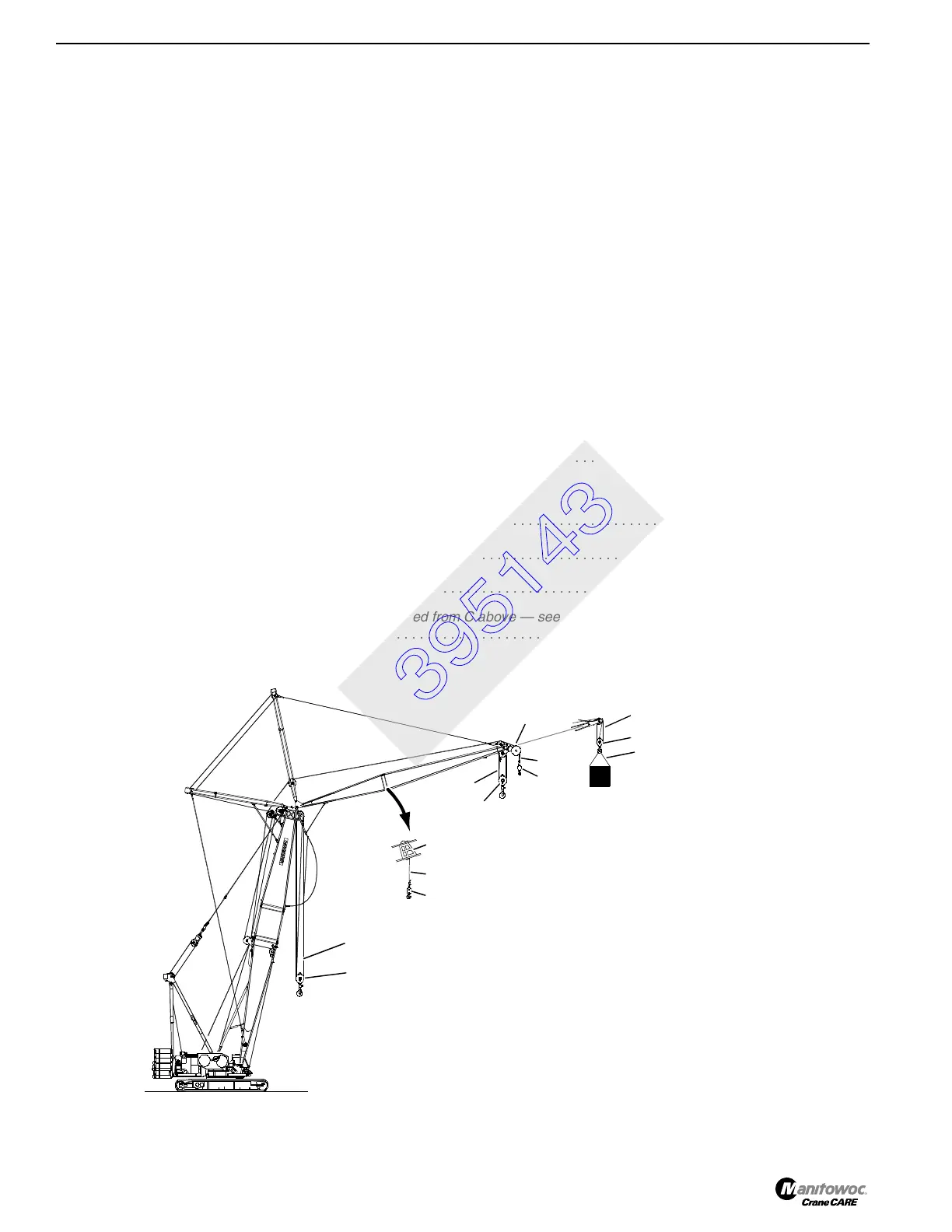
Worksheet F – Determining Total Load and Maximum Working Radius From Fixed Jib Point on Luffing Jib
DESCRIPTION WEIGHT
Component Weights
1 Load Block/Hook and Weight Ball
(below fixed jib point)
. . . . . . . . . . . . . . . . . . . . . . . . . . . . . . . . . . . . . .
___________
2 Upper Luffing Jib Point
(from capacity chart if noted)
. . . . . . . . . . . . . . . . . . . . . . . . . . . . . . . . . . . . . . . .
___________
3 Load Block/Hook and Weight Ball
(below upper luffing jib point, if installed)
. . . . . . . . . . . . . . . . . . . . . . .
___________
4 Load Block/Hook and Weight Ball
(below lower luffing jib point, if installed)
. . . . . . . . . . . . . . . . . . . . . . .
___________
5 Intermediate Fall Point
(see Intermediate Fall Deduct Table in capacity chart)
. . . . . . . . . . . . . . . . . . . . .
___________
6 Load Block/Hook and Weight Ball
(below intermediate fall point)
. . . . . . . . . . . . . . . . . . . . . . . . . . . . . . .
___________
7 Load Block/Hook and Weight Ball
(below lower boom point)
see Note 1: . . . . . . . . . . . . . . . . . . . . . . . . .
___________
8
Total Weight of Slings and Other Lifting Equipment Below Fixed Jib Point, Upper Luffing Jib Point, Lower
Luffing Jib Point, Intermediate Fall Point, and Lower Boom Point . . . . . . . . . . . . . . . . . . . . . . . . . . . . . . .
___________
9
Total Weight of Wire Rope Below Fixed Jib Point, Upper Luffing Jib Point, Lower Luffing Jib Point,
Intermediate Fall Point, and Lower Boom Point
(see Load Line or Wire Rope Specifications Chart for
weight of wire rope)
. . . . . . . . . . . . . . . . . . . . . . . . . . . . . . . . . . . . . . . . . . . . . . . . . . . . . . . . . . . . . . . . . .
___________
Totals
A Total Component Weights
(ADD items 1-9 above)
. . . . . . . . . . . . . . . . . . . . . . . . . . . . . . . . . . . . . . . . . .
___________
B Weight of Load to be Lifted . . . . . . . . . . . . . . . . . . . . . . . . . . . . . . . . . . . . . . . . . . . . . . . . . . . . . . . . . . . .
___________
C Total Load to be Lifted
(ADD A and B above)
. . . . . . . . . . . . . . . . . . . . . . . . . . . . . . . . . . . . . . . . . . . . . .
___________
D
Maximum Working Radius
(for Total Load to be Lifted from C above — see
correct capacity chart)
. . . . . . . . . . . . . . . . . . . . . . . . . . . . . . . . . . . . . . . . . . . . . . . . . . . . . . . . . . . . . . . .
___________
A922
7, 8
9
9
4, 8
3, 8
9
5
6, 8
9
2
1
9
Note 1: Depending on jib length, some lower
boom point sheaves may have to be
removed.
See capacity chart for
detailed information
.
B
8
395143