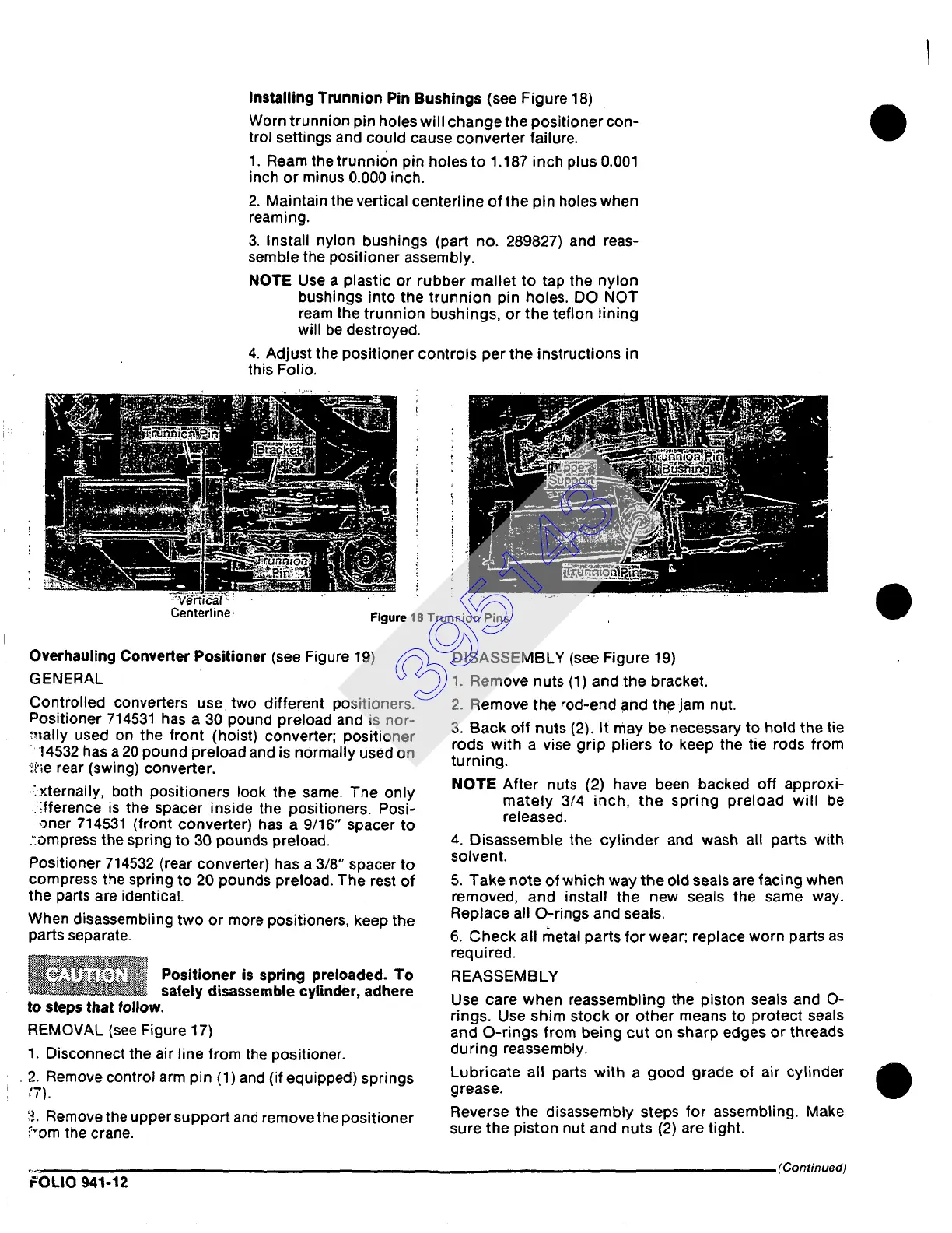
Installing Trunnion Pin Bushings
(see Figure
18)
Worn trunnion pin holes will change the positioner con-
trol settings and could cause converter failure.
1. Ream the trunnion pin holes to 1.187 inch plus 0.001
inch or minus 0.000 inch.
2. Maintain the vertical centerline of the pin holes when
reaming.
3. Install nylon bushings (part no. 289827) and reas-
semble the positioner assembly.
NOTE Use a plastic or rubber mallet to tap the nylon
bushings into the trunnion pin holes. DO NOT
ream the trunnion bushings, or the teflon lining
will be destroyed.
4. Adjust the positioner controls per the instructions in
this Folio.
Centerline, Figure 18 Trunnion Pins
Overhauling Converter Positioner
(see Figure 19)
GENERAL
Controlled converters use two different positioners.
Positioner 714531 has a 30 pound preload and is nor-
~',mlly used on the front (hoist) converter; positioner
. 14532 has a 20 pound preload and is normally used on
• ~P~e rear (swing) converter.
~ternally, both positioners look the same. The only
:ffference is the spacer inside the positioners. Posi-
,~ner 714531 (front converter) has a 9/16" spacer to
:.ompress the spring to 30 pounds preload.
Positioner 714532 (rear converter) has a 3/8" spacer to
compress the spring to 20 pounds preload. The rest of
the parts are identical.
When disassembling two or more positioners, keep the
parts separate.
~~ Positioner is
spring preloaded.
To
salely disassemble cylinder, adhere
to steps that follow.
REMOVAL (see Figure 17)
1. Disconnect
the air line from the positioner.
• 2. Remove control arm pin (1) and (if equipped) springs
:7}.
3. Remove the upper support and remove the positioner
~om the crane.
DISASSEMBLY (see Figure 19)
1. Remove nuts (1) and the bracket.
2. Remove the rod-end and the jam nut.
3. Back off nuts (2). It may be necessary to hold the tie
rods with a vise grip pliers to keep the tie rods from
turning.
NOTE After nuts (2) have been backed off approxi-
mately 3/4 inch, the spring preload will be
released.
4. Disassemble the cylinder and wash all parts with
solvent.
5. Take note of which way the old seals are facing when
removed, and install the new seals the same way.
Replace all O-rings and seals.
6. Check all metal parts for wear; replace worn parts as
required.
REASSEMBLY
Use care when reassembling the piston seals and O-
rings. Use shim stock or other means to protect seals
and O-rings from being cut on sharp edges or threads
during reassembly.
Lubricate all parts with a good grade of air cylinder
grease.
Reverse the disassembly steps for assembling. Make
sure the piston nut and nuts (2) are tight.
(Continued)
FOLIO 941-12
395143