MANITOWOC ENGINEERING, CO.
Division of The Manitowoc Company, Inc, Manitowoc, Wisconsin 54220
PRESSURE SWITCH ADJUSTMENT
All Models
(•
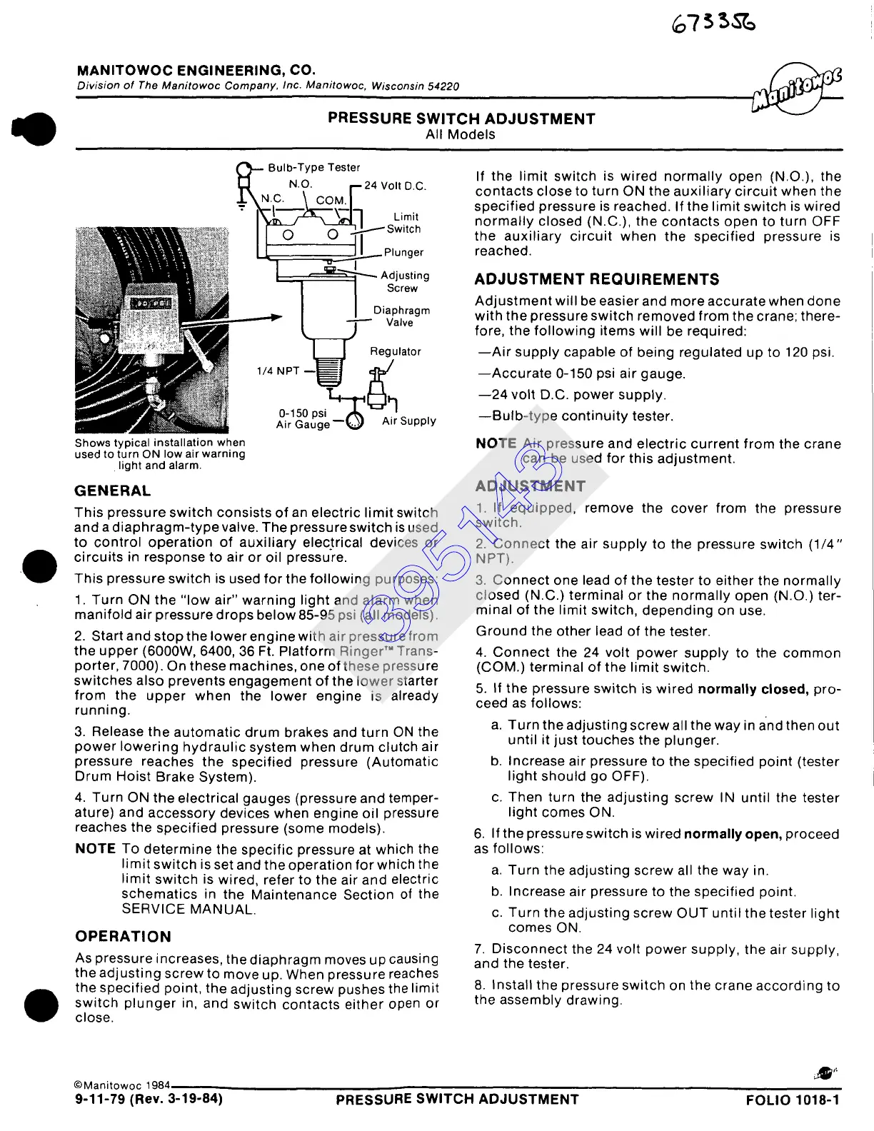
Bulb-Type Tester
N.O. f--24 Volt D.C.
±\Nc. \ coM/
-
I ,L
Limit
~i~~i~ ~ I ~ ~ ....~-.--~ Switch
~ ~ ~%~1~~ ~!:~,, P I u n g e r
~-~.~I~~¢~ i
•~~~
~ ~-~::~<~: ~~ Adjusting
~~ii I I Screw
I I Diaphragm
~.j~ Valve
Regulator
o- so
Air Gauge ~ ,~,k, Air Supply
Shows typical installation when
used to turn ON low air warning
light and alarm.
GENERAL
This pressure switch consists of an electric limit switch
and a diaphragm-type valve. The pressure switch is used
to control operation of auxiliary electrical devices or
circuits in response to air or oil pressure.
This pressure switch is used for the following purposes:
1. Turn ON the "low air" warning light and alarm when
manifold air pressure drops below 85-95 psi (all models).
2. Start and stop the lower engine with air pressure from
the upper (6000W, 6400, 36 Ft. Platform Ringer" Trans-
porter, 7000). On these machines, one of these pressure
switches also prevents engagement of the lower starter
from the upper when the lower engine is already
running.
3. Release the automatic drum brakes and turn ON the
power lowering hydraulic system when drum clutch air
pressure reaches the specified pressure (Automatic
Drum Hoist Brake System).
4. Turn ON the electrical gauges (pressure and temper-
ature) and accessory devices when engine oil pressure
reaches the specified pressure (some models).
NOTE
To determine the specific pressure at which the
limit switch is set and the operation for which the
limit switch is wired, refer to the air and electric
schematics in the Maintenance Section of the
SERVICE MANUAL.
OPERATION
As pressure increases, the diaphragm moves up causing
the adjusting screw to move up. When pressure reaches
the specified point, the adjusting screw pushes the limit
switch plunger in, and switch contacts either open or
close.
If the limit switch is wired normally open (N.O.), the
contacts close to turn ON the auxiliary circuit when the
specified pressure is reached. If the limit switch is wired
normally closed (N.C.), the contacts open to turn OFF
the auxiliary circuit when the specified pressure is
reached.
ADJUSTMENT REQUIREMENTS
Adjustment will be easier and more accurate when done
with the pressure switch removed from the crane; there-
fore, the following items will be required:
--Air supply capable of being regulated up to 120 psi.
--Accurate 0-150 psi air gauge.
--24 volt D.C. power supply.
--Bulb-type continuity tester.
NOTE
Air pressure and electric current from the crane
can be used for this adjustment.
ADJUSTMENT
1. If equipped, remove the cover from the pressure
switch.
2. Connect the air supply to the pressure switch (1/4"
NPT).
3. Connect one lead of the tester to either the normally
closed (N.C.) terminal or the normally open (N.O.) ter-
minal of the limit switch, depending on use.
Ground the other lead of the tester.
4. Connect the 24 volt power supply to the common
(COM.) terminal of the limit switch.
5. If the pressure switch is wired
normally closed,
pro-
ceed as follows:
a. Turn the adjusting screw all the way in and then out
until it just touches the plunger.
b. Increase air pressure to the specified point (tester
light should go OFF).
c. Then turn the adjusting screw IN until the tester
light comes ON.
6. If the pressure switch is wired normally open, proceed
as follows:
a. Turn the adjusting screw all the way in.
b. Increase air pressure to the specified point.
c. Turn the adjusting screw OUT until the tester light
comes ON.
7. Disconnect the 24 volt power supply, the air supply,
and the tester.
8. Install the pressure switch on the crane according to
the assembly drawing.
©Manitowoc 1984
Ap,,
9-11-79 (Rev. 3-19-84) PRESSURE SWITCH ADJUSTMENT FOLIO 1018-1
395143
 Loading...


