BRAKE PEDAL INSTALLATION AND SHAPING
New brake pedals must be hand fitted at assembly as
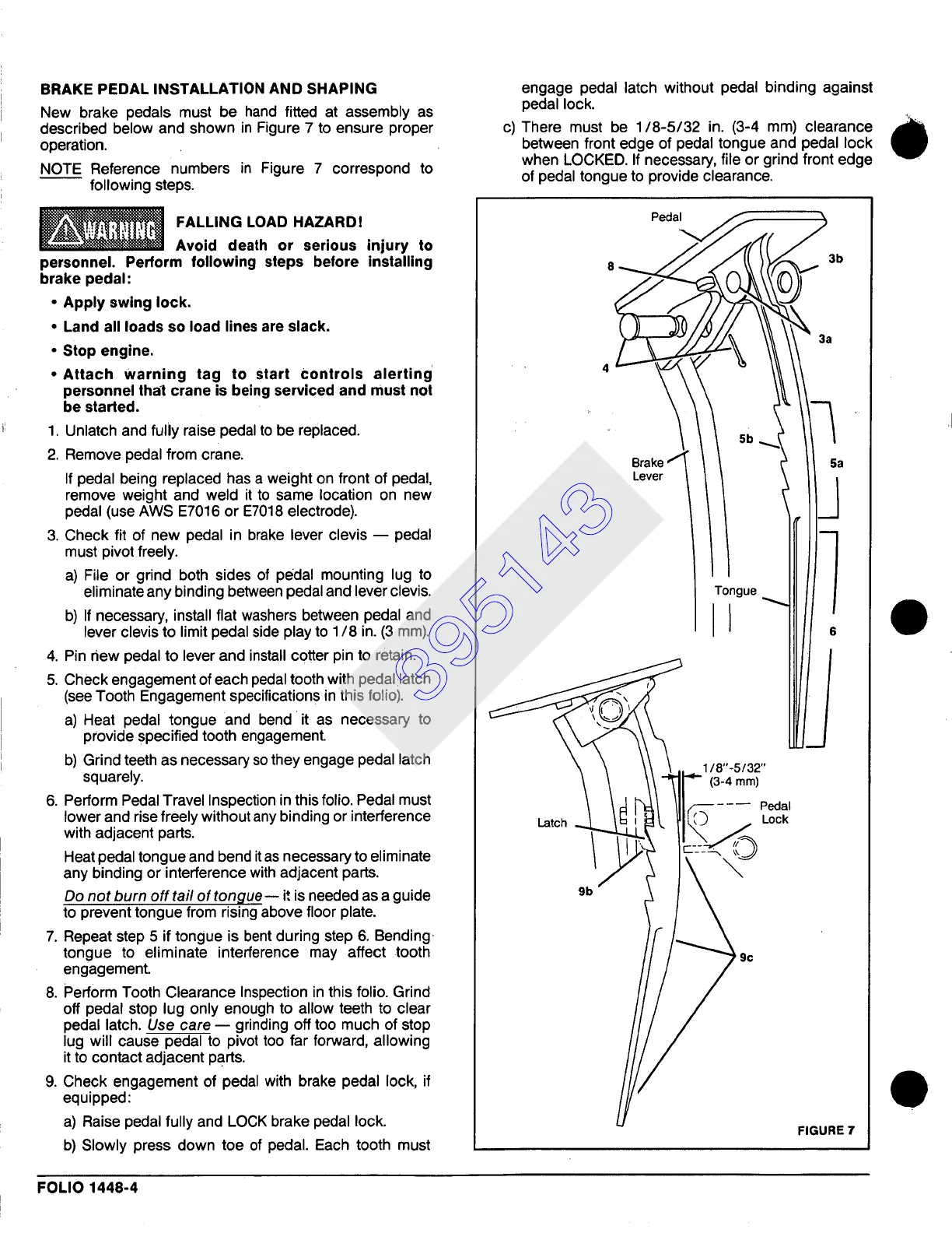
described below and shown in Figure 7 to ensure proper
operation.
NOTE Reference numbers in Figure 7 correspond to
following steps.
FALLING LOAD HAZARD!
Avoid death or serious injury to
personnel. Perform following steps before installing
brake pedal:
• Apply swing lock.
• Land all loads so load lines are slack.
• Stop engine.
• Attach warning tag to start Controls alerting
personnel that crane is being serviced and must not
be started.
1. Unlatch and fully raise pedal to be replaced.
2. Remove pedal from crane.
If pedal being replaced has a weight on front of pedal,
remove weight and weld it to same location on new
pedal (use AWS E7016 or E7018 electrode).
3. Check fit of new pedal in brake lever clevis u pedal
must pivot freely.
a) File or grind both sides of pedal mounting lug to
eliminate any binding between pedal and lever clevis.
b) If necessary, install flat washers between pedal and
lever clevis to limit pedal side play to 1/8 in. (3 mm).
4. Pin new pedal to lever and install cotter pi n to retain.
5. Check engagement of each pedal tooth with pedaHatch
(see Tooth Engagement specifications in this folio).
a) Heat pedal tongue and bend'it as necessary to
provide specified tooth engagement.
b) Grind teeth as necessary so they engage pedal latch
squarely.
6. Perform Pedal Travel Inspection in this folio. Pedal must
lower and rise freely without any binding or interference
with adjacent parts.
Heat pedal tongue and bend itas necessary to eliminate
any binding or interference with adjacent parts.
Do not burn off tail of tongue ~
it is needed as a guide
to prevent tongue from rising above floor plate.
7. Repeat step 5 if tongue is bent during step 6. Bending.
tongue to eliminate interference may affect tooth
engagement.
8. Perform Tooth Clearance Inspection in this folio. Grind
off pedal stop lug only enough to allow teeth to clear
pedal latch.
Use care --
grinding off too much of stop
lug will cause pedal to pivot too far forward, allowing
it to contact adjacent parts.
9. Check engagement of pedal with brake pedal lock, if
equipped:
a) Raise pedal fully and LOCK brake pedal lock.
b) Slowly press down toe of pedal. Each tooth must
FOLIO 1448-4
engage pedal latch without pedal binding against
pedal lock.
c) There must be 1/8-5/32 in. (3-4 mm) clearance
between front edge of pedal tongue and pedal lock
when LOCKED. If necessary, file or grind front edge
of pedal tongue to provide clearance.
Latch
9b
1/8"-5/32"
-i-- (3-4 mm)
~~ Pe6al
Lock
FIGURE 7
395143