MANITOWOC ENGINEERING, CO.
Division of The Manitowoc Company, Inc. Manitowoc, Wisconsin 54220
ENGINE COOLING SYSTEMS
PURPOSE
This folio describes operation of the engine cooling
systems used on Manitowoc cranes and provides main-
tenance procedures.
NOTE
For coolant capacities, refer to the Lubrication
Guide in the Service Manual. For information
pertaining to the engine and coolant specifica-
tions, refer to the engine manual.
OPERATION
Two types of cooling systems are used on Manitowoc
cranes: the basic diesel cooling system (Figure 1) and
the full deaeration cooling system (Figure 2).
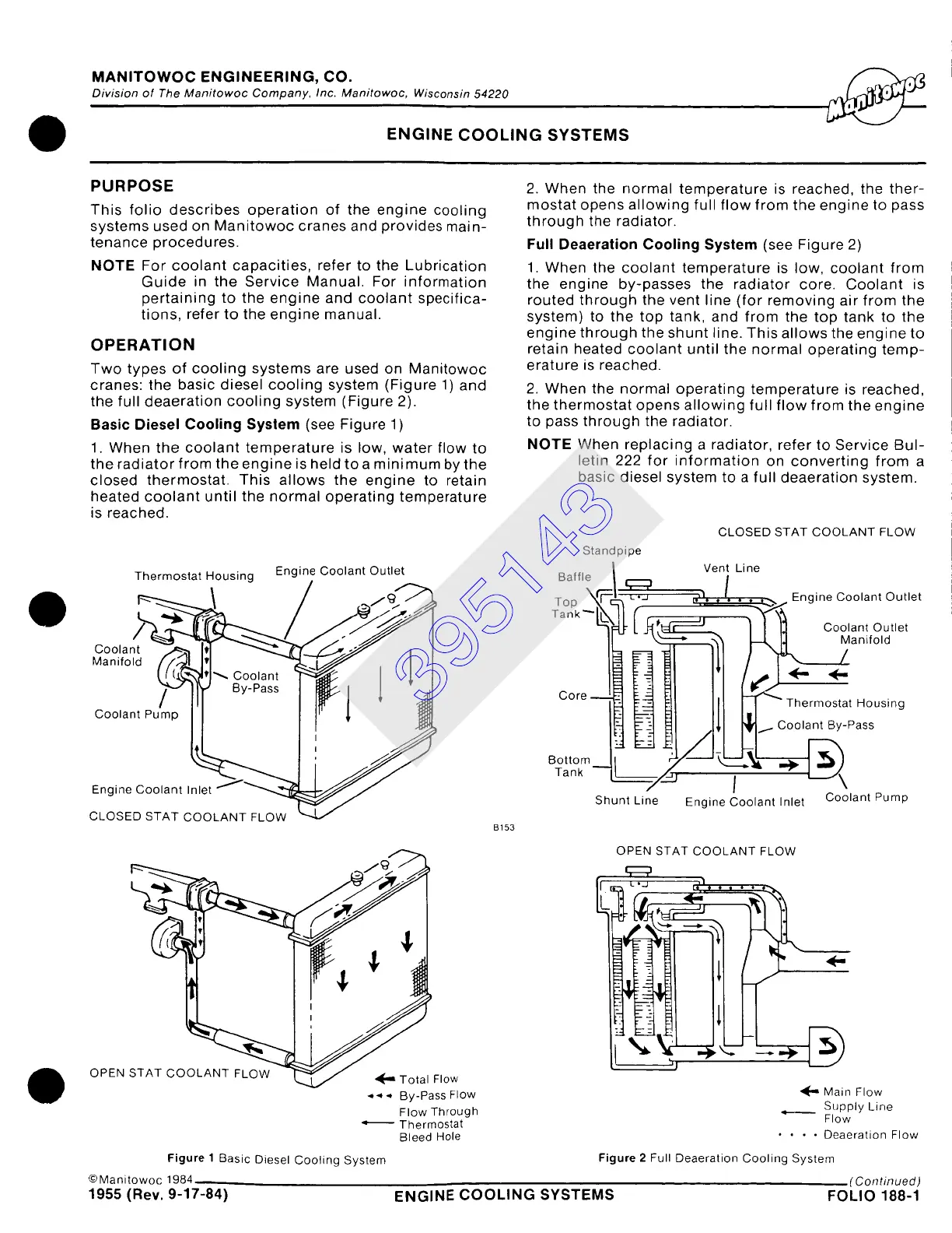
Basic Diesel Cooling System
(see Figure
1)
1. When the coolant temperature is low, water flow to
the radiator from the engine is held toa minimum by the
closed thermostat. This allows the engine to retain
heated coolant until the normal operating temperature
is reached.
2. When the normal temperature is reached, the ther-
mostat opens allowing full flow from the engine to pass
through the radiator.
Full Deaeration
Cooling System
(see Figure 2)
1. When the coolant temperature is low, coolant from
the engine by-passes the radiator core. Coolant is
routed through the vent line (for removing air from the
system) to the top tank, and from the top tank to the
engine through the shunt line. This allows the engine to
retain heated coolant until the normal operating temp-
erature is reached.
2. When the normal operating temperature is reached,
the thermostat opens allowing full flow from the engine
to pass through the radiator.
NOTE
When replacing a radiator, refer to Service Bul-
letin 222 for information on converting from a
basic diesel system to a full deaeration system.
Standpipe
CLOSED STAT COOLANT FLOW
Vent Line
Thermostat Housing Engine Coolant Outlet Baffle
~/.,~/,~ Top ~ =[j~~~~- Engine Coolant Outlet
Tank ~[~ '~ Coolant Outlet
" ~ ~lanifold
Coolant
Manifold
Core = | Thermostat Housing
Coolant Pump tnOkm .~~~l ~X l
I By-Pass
ICooa t
%
Engine Coolant Inlet
Shunt Line Engine Coolant Inlet Coolant Pump
CLOSED STAT COOLANT FLOW
OPEN STAT COOLANT FLOW
~ Total Flow
.,,4.,, By-Pass Flow
Flow Through
q Thermostat
Bleed Hole
Figure 1 Basic Diesel Cooling System
©Manitowoc 1984
1955 (Rev. 9-17-84)
B153
OPEN STAT COOLANT FLOW
I I i I
JJ '
'4[" Main Flow
~ Supply Line
Flow
.... Deaeration Flow
Figure 2 Full Deaeralion Cooling System
(Continued)
ENGINE COOLING SYSTEMS FOLIO 188-1
395143