Folio 931-11
WIRE ROPE INSTALLATION AND MAINTENANCE
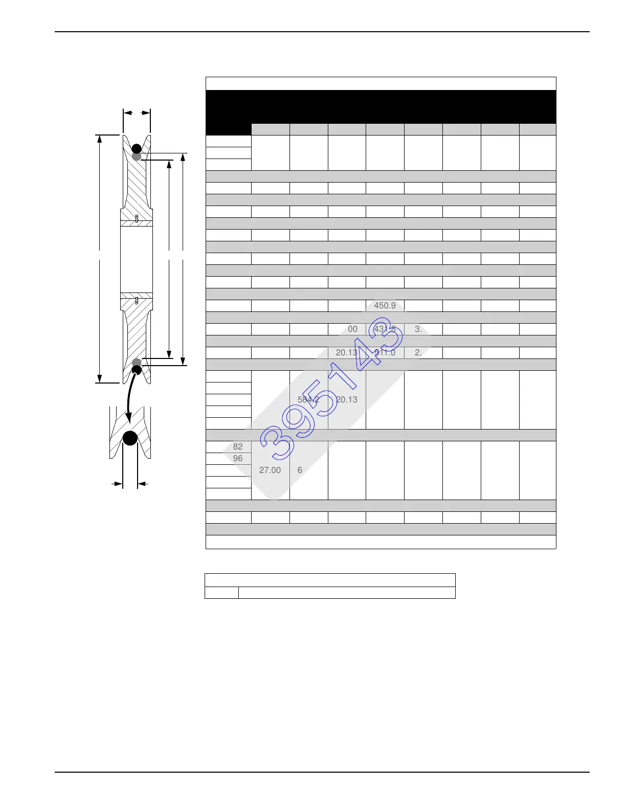
FIGURE 16
SHEAVE DATA
Sheave
Part No.
A
Outside
Diameter
B
Tread Diameter
1
C
Width
D
Rope Diameter
inch mm inch mm inch mm inch mm
912738
13.19 335.0 11.42 290.1 1.77 45.0 5/8 16631054
631056
631065 16.00 406.4 13.37 339.6 2.17 55.1 9/16 14
631071 16.00 406.4 13.88 352.6 2.17 55.1 5/8 16
631526 19.25 489.0 16.63 422.4 2.00 50.8 7/8 22
631527 19.25 489.0 16.63 422.4 2.00 50.8 5/8 16
631055 19.69 500.1 17.60 447.0 1.85 47.0 7/8 22
631067 19.69 500.1 17.75 450.9 1.97 50.0 3/4 19
631529 20.00 508.0 17.00 431.8 3.00 76.2 1 25
631519 23.00 584.2 20.13 511.0 2.25 57.2 7/8 22
631084
23.00 584.2 20.13 511.0 2.50 63.5 7/8 22
631102
631520
A00049
A00083
631082
27.00 685.8 23.00 584.2 3 76.2 1 28
631096
631103
A00050
A00051
631100 30.00 762.0 27.00 685.8 3.00 76.2 1-1/8 29
1
If tread print exists in root of sheave groove, measure to maximum tread diameter.
A B
C
D
E
REPLACEMENT DATA
E 3/16" (4.8 mm) Maximum from Original Tread Diameter
395143