MANITOWOC ENGINEERING
CO.
Division of The Manitowoc
Company,
Inc. Manitowoc, Wisconsin 54220
TELESCOPIC AIR CUSHIONED BOOM STOP
All Models
GENERAL
The telescopic air cushioned boom stop
consists
of a single
or double tube assembly on both sides of the boom. The
tubes are pin connected to the boom butt and to the A-frame,
the rotating bed, or the boom carder. Each tube assembly
consists of an upper tube, a lower tube with an air cylinder,
and piping connected between the cylinders and the air
manifold of the crane.
The telescopic air cushioned boom stop is provided for the
following purposes:
•
To
stop the boom smoothly.
• To prevent the boom rigging from pulling the boom back
when traveling or setting loads.
• To assist in moving the boom forward when lowering the
boom from a high angle.
NOTE The telescopic air cushioned boom stop also provides
a physical stop which, in the event of an accident,
aids in protecting the operator and minimizing crane
damage by causing the boom to buckle at a point
above the operator's cab.
Do
not operate crane with
tele-
scopic
air cushioned boom stop
removed.
Telescopic air cushioned boom stop is not designed
to stop boom. Be sure automatic boom stop is oper-
ating properly (see Automatic Boom Stop
Folio).
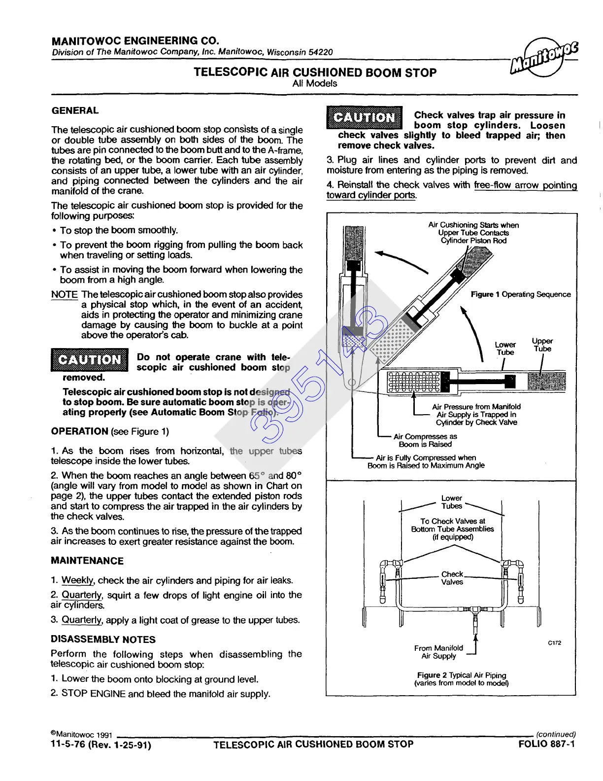
OPERATION
(see Figure 1)
1. As the boom rises from horizontal, the upper tubes
telescope inside the lower tubes.
2. When the boom reaches an angle between 65 ° and 80 °
(angle will vary from model to model as shown in Chart on
page 2), the upper tubes contact the extended piston rods
and start to compress the air trapped in the air cylinders by
the check valves.
3. As the boom continues to rise, the pressure of the trapped
air increases to exert greater resistance against the boom.
MAINTENANCE
1. Weekly, check the air cylinders and piping for air leaks.
2. Quarterly, squirt a few drops of light engine oil into the
air cylinders.
3. Quarterly, apply a light coat of grease to the upper tubes.
DISASSEMBLY
NOTES
Perform the following steps when disassembling the
telescopic air cushioned boom stop:
1. Lower the boom onto blocking at ground level.
2. STOP ENGINE and bleed the manifold air supply.
Check valves
trap air pressure
in
boom stop cylinders. Loosen
check valves slightly to bleed trapped air;, then
remove check
valves.
3. Plug air lines and cylinder ports to prevent dirt and
moisture from entering as the piping is removed.
4. Reinstall the check valves with free-flow arrow pointing
toward cylinder ports.
Air Cushioning Stmb when
Upper Tube Contacts
Cylinder Piston Rod
Figure I Operaling Sequence
Lower
Tube
--I~~es~re from Manifold
Air Supply is Trapped in
Cylinder by Check Valve
I ~ Air Compresses as
Boom is Raised
Air is Fully Compressed when
Boom is Raised to Maximum Angle
Upper
Tube
Lower
/ Tub~
BoTo°mCTuhC<~k .~ bla~es J
Figure 2 Typical Air Piping
(vades from model to model)
c172
©Manitowoc 1991
(continued)
11-5-76 (Rev. 1-25-91) TELESCOPIC AIR CUSHIONED BOOM STOP FOLIO 887-1
395143
 Loading...


