Manitowoc Engineering Co.
furnished depends upon the Boom Top, or Head used, and
the date of manufacture.
-INSTALL THE JIB STOP furnished.
PENDANT TYPE JIB STOPS are pinned to Lugs below
the Boom Point, and to the pivoted "Adjusting Bar" plates
on the lower Jib Butt Lugs. Pin through the hole in the
Adjusting Bar plate that will give the Least slack or some
preloading for 0 ° and 10 o Jib Offset. (Separate pendants
are provided for 0O and 10 o Offset.) When the Jib is
supported entirely by the Backstay Pendants for 20 o
Offset, no tension is required on the Jib Stop Pendants.
(Jib Stop Pendants for 10 o Offset is also used for 20 o
Offset. (See Fig. 1112-9, 10, 12 and 14.)
COMPRESSION-TYPE, CUSHIONED JIB STOPS are in-
stalled above the Jib Pivoting Pin, and are pinned between
the 22-22A Hammerhead Lugs and the upper Jib Butt
Lugs. A compressible internal rubber member permits
preloading the rigged Jib-Boom assembly to a specified
amount.
Install Pin "A" in the hole shown to, the Jib Offset used.
(Fig. 1112-13.) Raise the Boom to clear the Jib of any
ground support. Adjust the Clevis outwardly one full turn
beyond the point where the holes in the Clevis and Jib
Butt are aligned. Drive in Pin "B", which will force the
Jib downward enough for the proper preload.
STRAP-TYPE JIB STOPS, Fig. 1112-11, are used in tension
between the lower Jib Butt Lug and the hammerhead, as
shown. Pin both straps on each side to the Jib and Boom.
With the weight of the Jib fully supported by the Pendants,
pin the Straps together through the holes provided for
the Jib Offset Used.
(6
OFFSETS IN FEET
In figuring a job and the reach of the Jib with various
offsets, it is often convenient to know the Offset Angle in
terms of feet far the various angles and Jib lengths. These
Offset dimensions are shown in Fig. i112-8 for Straight
and Offset Boom Tops. (Also, see Fig. 1112-2.)
JIB OFFSETS IN FEET
Appiies to the following Booms:
#8, #9, #9A, #17, #22 & #22A Open Throat
(Straight) Booms
JIB
LENGTHS
DEGREES
OF JIB
30 Ft. 40 Ft.
ANGLE
0 1' i'
10 6' i, 8'
20 '11' 15'
50 Ft. 60 Ft.
1' 0'
9,~'. lO'
18'
20~'
FOR: #17 BOOM W/4 DEGREE OFFSET TOP-
0 '/~' I':
I '~
0'
10 6' 8' ' 9~" 101/2;
20 11' 15' 18' 21'
FOR: #9 #9A, #22, & #22A BOOMS
w/4~ DEGREE OFFSET TOPS
0 I'
I~'
1'
10 6' 8' 10'
20 11~'
15~'
18~'
0'
101/~ '
21'
FIG. 1112-8
For Offsets of Booms
not
given
above,
see MEC Engin-
eering Drawings.
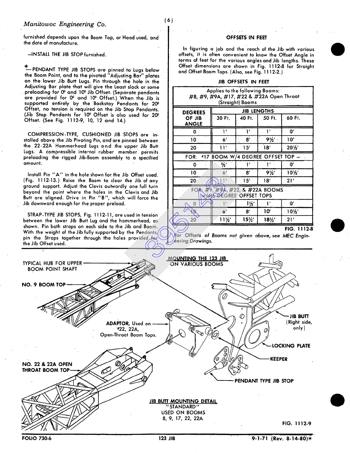
TYPICAL HUB FOR UPPER
BOOM POINT SHAFT
MOUNTING THE 1~3 ~IIB
ON VARIOUS BOOMS
NO. 9 BOOM
ADAPTOR,
Used on
#22, 22A,
Open-Throat Boom Tops.
NO. 22 • 22A
THROAT BOOM
~
% J//
JIB BUTT
MOUNTING DETAIL
"STANDARD"
USED ON BOOMS
8, 9, 17, 22, 22A
,•"-
J IB BUff
( Right side,
only)
PLATE
~'KEEPER
PENDANT TYPE
JIB STOP
FIG. 1112-9
FOLIO
730-6 123 JIB ~ ' 9-1-71 (Rev. 8-14-80)*
395143
 Loading...


