Published 5-3-2016, Control # 555-02 4-11
RT530E-2 OPERATOR’S MANUAL SET-UP AND INSTALLATION PROCEDURES
13
12
14
5
4
3
2
1
11
15
10
9
8
7
6
6717-2
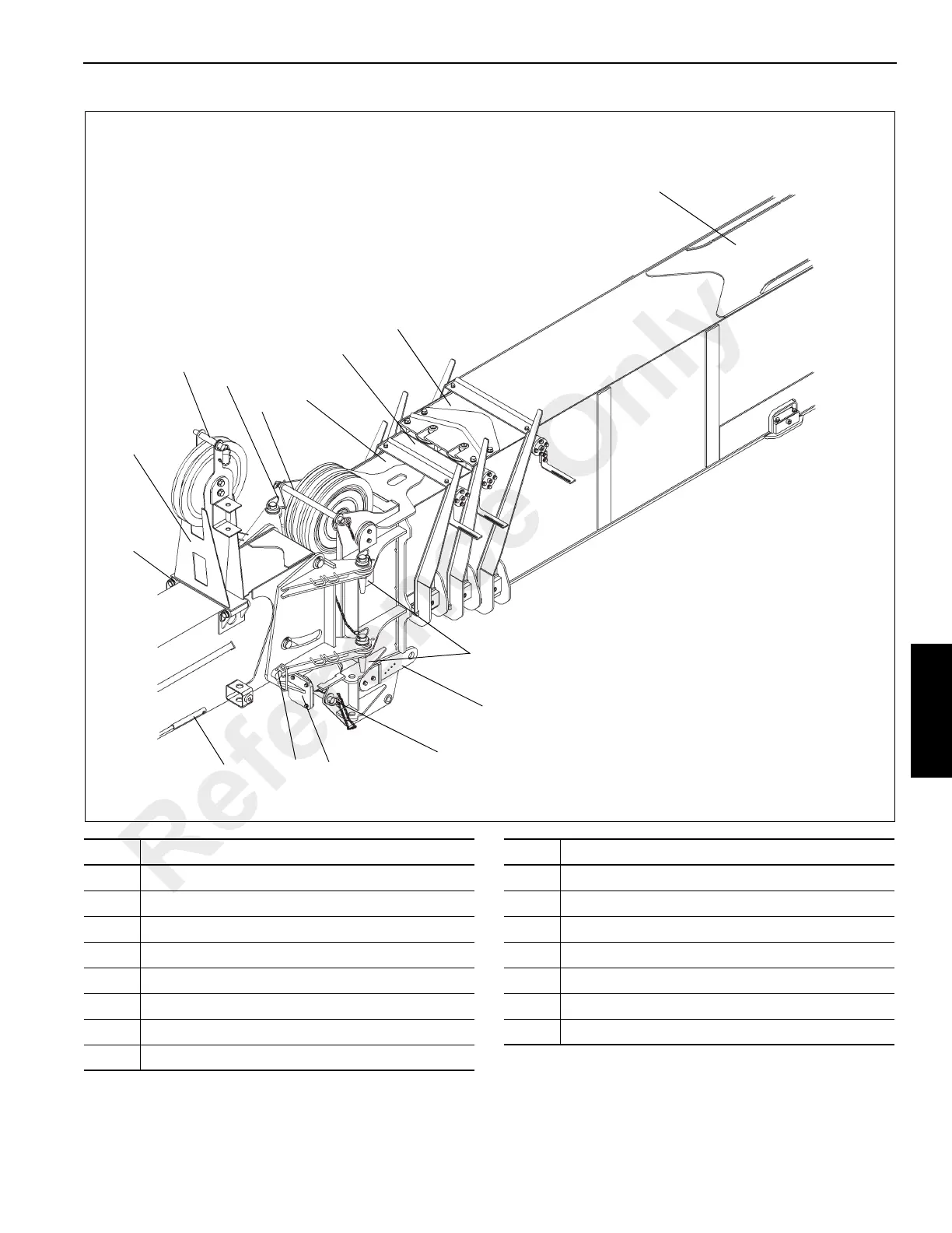
FIGURE 4-11
Item Description
1 Boom Base Section
2 Inner Mid Section
3 Outer Mid Section
4 Fly Section
5 Upper Sheave Cable Retainer
6 Left Side Attachment Pins
7 Boom Nose Dead End Lug
8 Lower Sheave Cable Retainer
Item Description
9 Alignment Jack
10 Offset Pin
11 Mast Assembly Stowage Pin
12 Mast Assembly
13 Mast Assembly Cable Retainer
14 Right Side Attachment Pins
15 Jack Handle
Reference Only
 Loading...


