GROVE Published 1-20-2017, Control # 468-02 5-5
CD5515-2/YB5515-2 OPERATOR MANUAL ATTACHMENTS
BOOM EXTENSION
Installing the Boom Extension
To use the boom extension it must be attached to the boom
head. The boom extension can be attached by performing
the following procedure:
1. Completely retract the booms.
2. Remove the hook block from the hoist wire rope.
3. Remove the two pins from the boom nose Figure 5-8.
4. Remove the wire rope from the sheaves. Operate the
hoist control to release more wire rope.
5. Remove the pin from the boom extension anchor
bracket (Location No. 1 in Figure 5-9).
a. Remove the two pins from the extension link at
location No. 2.
b. Remove the outmost retaining pin at location No. 3
and flip up the deflector sheave bracket into its
upright position.
c. Install the pin at location No. 4 to secure the
deflector sheave bracket in place.
6. Swing the boom extension at the swing arm pivot point
(No. 5). Align and engage the extension link with the
boom head at location No. 6. Install the two pins
removed in the extension link.
NOTE: It may be necessary to extend the boom slightly to
align the holes for installation of the pins.
7. Remove the pin at locations No. 7 and No. 8. Swing the
boom extension forward (No. 9). Install the pin from No.
7 at location No. 11.
8. Engage the extension link with the boom head and
install the pins from No. 8 at location No. 10. Swing the
swing arm back towards the boom (No. 12) and install
the pin from No. 1 at location No. 13.
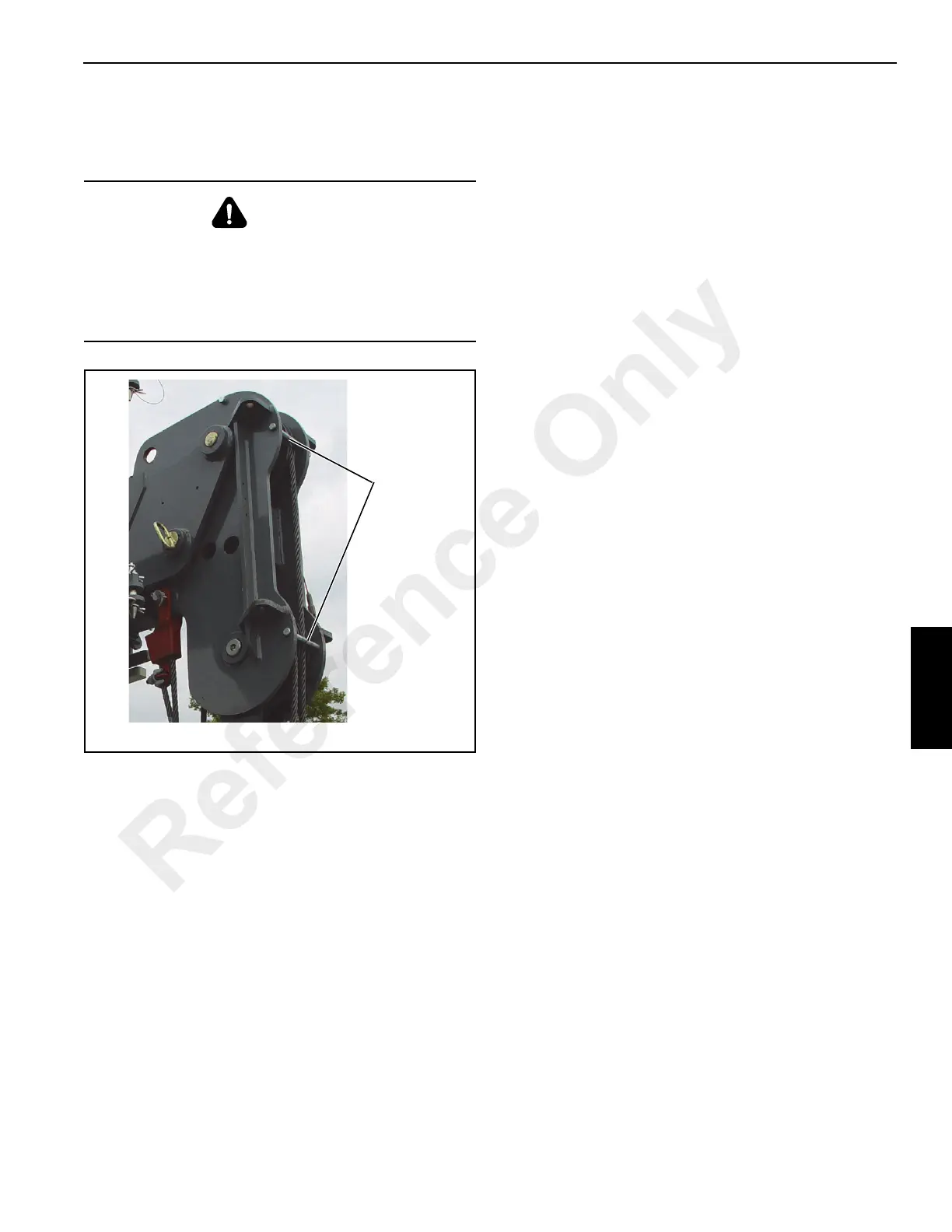
9. Install the wire rope over the deflector sheave at the
base of the jib boom.
10. Remove the two pins (1 and 2, Inset, Figure 5-9), and
place the wire rope over sheave (3). Install pins (1 and
2).
11. Disconnect the wires from the anti-double blocking
switch in the boom head. Connect the wire in the jib
boom to the wires on the main boom.
12. Attach the down haul weight to the wire rope using
wedge and socket per instructions later in this section.
Adjusting the Boom Extension Angle
The boom extension can be positioned to any one of three
angles Figure 5-3. For adjustment procedures, see Adjusting
the Optional Boom Extension Offset, page 5-3.
Stowing the Boom Extension
To stow the boom extension, perform the following
procedure:
1. Remove the hook and ball.
2. Remove the two pins (1 and 2, Inset, Figure 5-9).
3. Operate the hoist control to wind excess wire rope onto
hoist drum. Install pins removed in step 2.
4. Disconnect the anti-double blocking switch wires.
5. Remove pins at location No. 10, Figure 5-9, and swing
the boom extension backward. Install pins removed at
location No. 10 in extension link to prevent them from
becoming lost.
6. Remove the pin at location No. 4 and swing the deflector
sheave to the left side of the boom. Install pin at location
No. 3.
WARNING
Crushing Hazard!
The boom extension is very heavy. Use another crane or
hoist to support the extension from falling when the pivot
anchor pin is removed and adjusting the extension angle.
A falling boom can cause serious injury or death.
Reference Only
 Loading...


