Grove Published 1-20-2017, Control # 468-02 3-19
CD5515-2/YB5515-2 OPERATOR MANUAL OPERATING CONTROLS AND PROCEDURES
Outriggers fully retracted or outriggers fully extended are the
only outrigger positions documented on the Load Charts.
Each proximity switch senses the presence of it’s respective
outrigger beam until the beam reaches it’s fully extended
position.
Proximity switch outputs are wired in series such that when
all outrigger beams are fully extended, each proximity switch
will no longer sense presence of its outrigger beam, the
output contact will then close illuminating the green indicator
on the control panel signaling all outriggers are fully
extended and lifts can be made per “outriggers fully
extended” Load Chart.
Any outrigger beam not fully extended or functional failure of
any proximity switch will cause the indicator to not illuminate,
indicating outrigger beams are not fully extended and lifts
can only be made per the “outriggers retracted” or “on
rubber” Load Charts.
Outrigger beam position monitor is not interfaced with the
rated capacity limiter system (if equipped), the crane
operator is responsible for selecting the correct load chart.
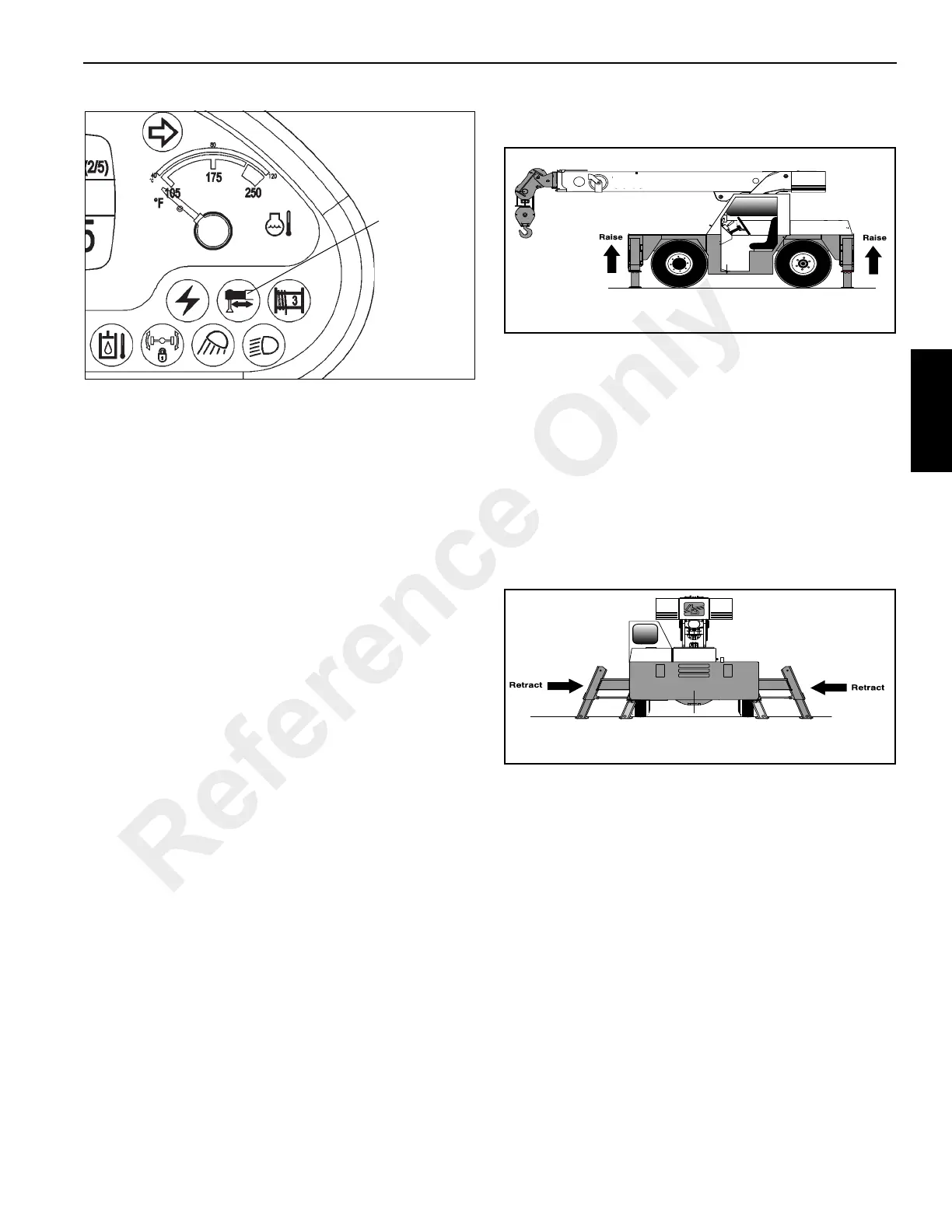
Raising the Stabilizers
1. Place the Outrigger/Stabilizer selector switches (1,
Figure 3-26) in the stabilizer position—push the bottom
of the switch.
2. Run the engine at idle speed (accelerator pedal
released).
3. Push the bottom of the Extend/Retract Switch (2).
4. Press the accelerator pedal to increase the engine
speed, which will accelerate the upward movement of
the stabilizers (Figure 3-29). Release the accelerator
pedal and the switch when the stabilizers are fully
retracted.
Retracting the Outriggers
1. Place the Outrigger/Stabilizer selector switches (1,
Figure 3-26) in the outrigger position—push the top of
the switch.
2. Run the engine at idle speed (accelerator pedal
released).
3. Push the bottom of the Extend/Retract Switch (2).
4. Press the accelerator pedal to increase the engine
speed, which will accelerate the inward movement of the
outriggers (Figure 3-30). Release the accelerator pedal
and the switch when the outriggers are fully retracted.
Operating the Boom Controls
Four levers in the operator’s cab control the boom functions.
See Figure 3-1. These levers are connected to the main
control valves by hydraulic pilot lines. The function of each
control is shown in Figure 3-31.
When operating each control, press the accelerator pedal to
increase engine speed to maximum RPM. Slowly move the
control lever. The further the control lever is moved the faster
the function will operate. To stop function movement, move
the control lever to the neutral position, then lower the engine
speed to idle.
Reference Only
 Loading...


