GROVE Published 1-20-2017, Control # 468-02 5-1
CD5515-2/YB5515-2 OPERATOR MANUAL ATTACHMENTS
SECTION 5
ATTACHMENTS
SECTION CONTENTS
Pivoting Boom Head (Optional). . . . . . . . . . . . . . . 5-1
Boom Head Positions . . . . . . . . . . . . . . . . . . . . . . 5-1
Changing the Optional Boom Head Position
(No Extension) . . . . . . . . . . . . . . . . . . . . . . . . . . . 5-2
Adjusting the Optional Boom Extension Offset. . . 5-3
Hook Block . . . . . . . . . . . . . . . . . . . . . . . . . . . . . . . 5-3
Removing the Hook Block. . . . . . . . . . . . . . . . . . . 5-3
Installing the Hook Block . . . . . . . . . . . . . . . . . . . 5-4
Boom Extension . . . . . . . . . . . . . . . . . . . . . . . . . . . 5-5
Installing the Boom Extension . . . . . . . . . . . . . . . 5-5
Stowing the Boom Extension. . . . . . . . . . . . . . . . . 5-5
Searcher Hook Assembly . . . . . . . . . . . . . . . . . . . . 5-7
Installation . . . . . . . . . . . . . . . . . . . . . . . . . . . . . . . 5-7
Removal. . . . . . . . . . . . . . . . . . . . . . . . . . . . . . . . . 5-7
Down Haul Weight. . . . . . . . . . . . . . . . . . . . . . . . . . 5-8
Installing the Down Haul Weight . . . . . . . . . . . . . . 5-8
Removing the Down Haul Weight . . . . . . . . . . . . . 5-8
Installing Cable On The Hoist. . . . . . . . . . . . . . . . . 5-9
Wire Rope Wedge Socket . . . . . . . . . . . . . . . . . . . 5-10
4 Part Wire Rope Reeving. . . . . . . . . . . . . . . . . . . 5-12
PIVOTING BOOM HEAD (OPTIONAL)
Boom Head Positions
The optional pivoting boom head, installed on the optional
four section boom, can be adjusted to five angle positions,
four of which are used when there is no boom extension
attached and two when a boom extension is attached.
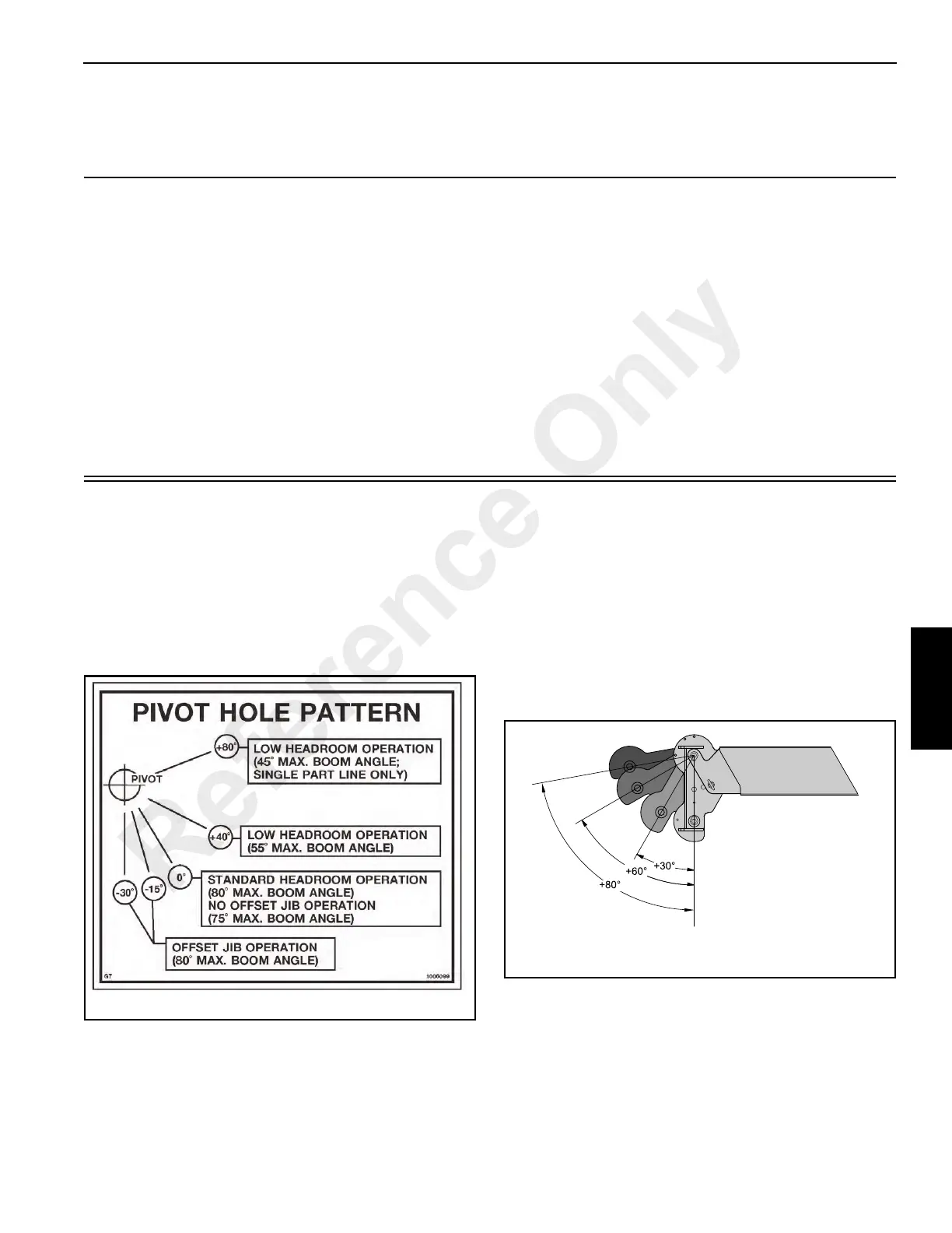
There are limitations to the boom elevation when the boom
head is pivoted. Refer to Figure 5-1, Pivot Hole Pattern decal
(also attached to boom head) for these limitations.
Positions When No Boom Extension is Attached
The 0° boom head position is the standard position. The 30°,
60°, and 80° (Figure 5-2) positions can be used when
clearance requirements dictate a lower boom head profile.
All positions can be used with either single or two part line
setups.
Positions When Boom Extension is Attached
The minus 15° and minus 30° boom head angles are used to
offset the boom extension. See Figure 5-3.
Reference Only
 Loading...


