ATTACHMENTS CD5515-2/YB5515-2 OPERATOR MANUAL
5-2 Published 1-20-2017, Control # 468-02
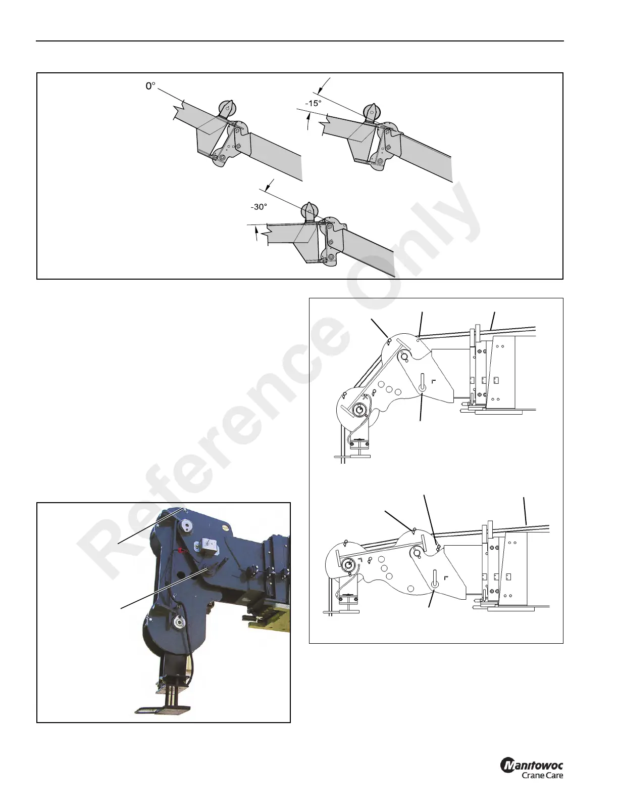
Changing the Optional Boom Head Position
(No Extension)
1. Lower and retract the boom.
2. Lower the block or ball to the ground to take weight off of
the wire rope and boom head.
3. Remove the retaining clip from the rope retention pin,
remove the rope retention pin from the top of the boom
head (Figure 5-4).
4. Remove the lynch pin and the pivot lock pin (Figure 5-4).
5. Position the pin hole in the boom head to align with the
hole for the desired angle (see Figure 5-2). Insert the
pivot lock pin through the holes and install the lynch pin.
6. Install the rope retention pin and retaining clip into the
top of the boom head (Figure 5-4).
7. When offsetting boom head (Figure 5-5) to +40° run
rope above pin #1 and between pin #2 and sheave
wheel.
8. When offsetting boom head (Figure 5-5) to +80° run
rope above pin #1 and between pin #2 and sheave
wheel.
7407-34
FIGURE 5-4
Pivot Lock Pin
Rope Retention
Pin
FIGURE 5-5
Pin 1
8508-2
8508-1
Pivot Lock Pin
Pin 2
Pin 1
Pin 2
+80° Offset
+40° Offset
Wire Rope
Wire Rope
Pivot Lock Pin
Reference Only
 Loading...


