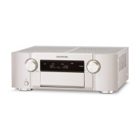
Do you have a question about the Marantz SR8001 and is the answer not in the manual?
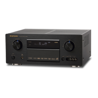
| Type | AV Receiver |
|---|---|
| Channels | 7.1 |
| Total Harmonic Distortion | 0.08% |
| Input Impedance | 47 kOhms |
| Input Sensitivity | 200 mV |
| HDMI Inputs | 3 |
| HDMI Outputs | 1 |
| Component Video Inputs | 3 |
| Component Video Outputs | 1 |
| Analog Audio Inputs | 6 |
| THX Certified | No |
| Power Output | 125W per channel (8 ohms, 20Hz-20kHz, 0.08% THD) |
| Frequency Response | 10 Hz - 100 kHz |
| Signal-to-Noise Ratio | 100dB |
| Digital Audio Outputs | 1 (optical) |
| Surround Sound Formats | DTS-ES, DTS Neo:6, Dolby Pro Logic IIx |
| Video Upconversion | Yes |
| Weight | 17 kg |
Details specifications for the FM tuner.
Details specifications for the AM tuner.
Details specifications for the HDMI interface.
Details specifications for the audio output and input.
Details specifications for video processing and output.
Provides general specifications like power and weight.
Lists included accessories with the unit.
Provides physical dimensions of the unit.
Covers THX Surround EX and THX Select2 technologies.
Details DTS, Neo:6, and DTS-ES Extended Surround formats.
Explains Dolby Digital, Pro Logic IIx, and Dolby Headphone.
Covers Circle Surround II, HDCD, Audyssey MultEQ, and HDMI.
Procedure for aligning idling current for power amplifier channels.
Accessing and checking firmware versions and segment modes.
Describes EEP-ROM communication errors and troubleshooting.
Describes +5V supply errors and troubleshooting steps.
Explains protection mode detection and causes.
Covers other detection issues not indicated on FL display.
Step-by-step guide for downloading and installing software.
Procedure to update MAIN CPU software to internal Flash-ROM.
Procedure to update DSP software to 8M Flash-ROM.
Procedure to update HDMI CPU software to internal Flash-ROM.
Schematic diagram for the Video PWB.
Schematic diagram for the Component PWB.
Schematic diagram for the HDMI PWB (Part 1/4).
Schematic diagram for the Input PWB.
Schematic diagram for the DSP PWB (Part 1/2).
Schematic diagram for the Amplifier (AMP) PWB.
Schematic diagram for the Power PWB A.
Schematic diagram for the Front PWB A.
Schematic diagram for the Standby PWB A.
Schematic diagram for the RS-232C PWB.
Schematic diagram for the 7.1 Channel Preout PWB A.
Component layout for Component PWB A.
Component layout for Component PWB B.
Pin description and data for IC11 (HD64F2505).
Pin description and data for IC90 (HD64F36087HV).
Pin description and data for IC41 (CS4382A-CQ).
Pin description and data for IC33 (TMS320DA708).
Pin description and data for IC34 (M29W800DT70N).
Pin description and data for IC35 (SiI 9030CTU-7).
Pin description and data for IC36 (TC74VCX157FT).
Pin description and data for IC39 (TC7WH157FU).
Lists various resistors with their specifications and part numbers.
Lists various capacitors with their specifications and part numbers.
Lists electrolytic capacitors with their specifications and part numbers.
Lists film capacitors with their specifications and part numbers.
Highlights safety precautions for component replacement.