6A-34 POWER TRIM 90-13645--2 495
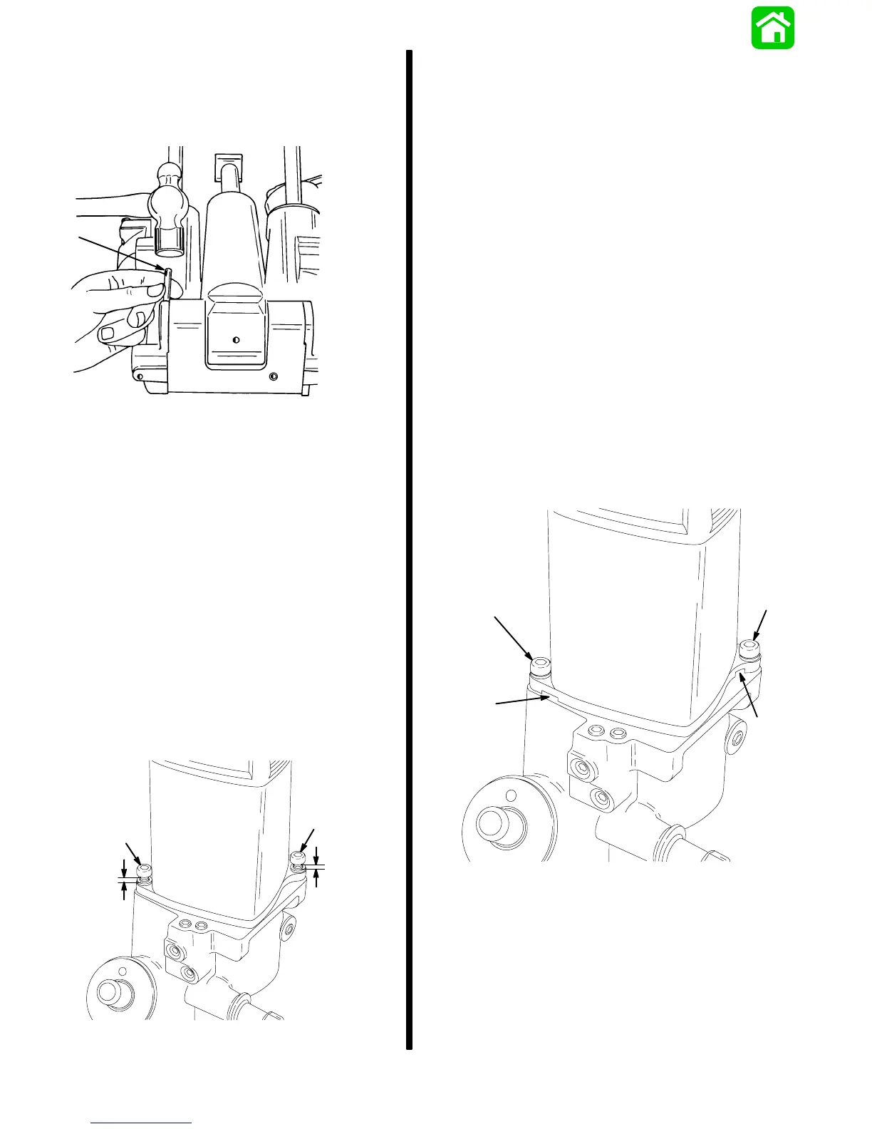
4. Install pin. Drive pin in until flush.
Install Power Trim assembly on engine, refer to
“Installation” instructions in “Power Trim Assem-
bly Removal and Installation,” preceding.
51356
a
a - Pin (Drive Against Knurled End)
Pump Replacement
IMPORTANT: The pump is not rebuildable. If pump
is defective, replace as an assembly.
NOTE:
Power Trim assembly does not have to be re-
moved from engine to replace pump.
1. Disconnect trim pump motor wires, and remove
starboard transom bracket from engine; refer to
“Removal” instructions in “Power Trim Assembly
Removal and Installation,” preceding.
Unseat motor and pump assembly from housing
as follows:
OPERATIVE TRIM MOTOR
Loosen 2 bolts until 1/4 (6mm) of each bolt is ex-
posed. Do not remove bolts.
18458
a
a
1/4″
1/4″
a - Bolts
Tighten manual release valve to full right (clockwise).
Operate trim motor in “Up” direction by connecting
trim motor wires to a 12-volt battery [BLUE wire to
POSITIVE (+) terminal and BLACK wire to
NEGATIVE (–) terminal].
Slowly remove fill screw to bleed pressure from
reservoir.
From a full closed (clockwise) position, slowly turn
manual release valve counterclockwise four turns to
bleed remaining pressure from system.
Remove 2 bolts and lockwashers.
Lift motor and pump assembly from housing.
INOPERATIVE TRIM MOTOR
Slowly remove fill screw to bleed pressure from
reservoir.
From a full closed (clockwise) position, slowly turn
manual release valve counterclockwise four turns to
bleed remaining pressure from system.
Remove 2 bolts and lockwashers.
Using 2 screwdrivers, pry up on motor at slots.
18461
b
c
b
c
b - Bolts
c - Slots