7A-5ENGINE ATTACHMENTS90-13645--2 495
a
b
c
d
e
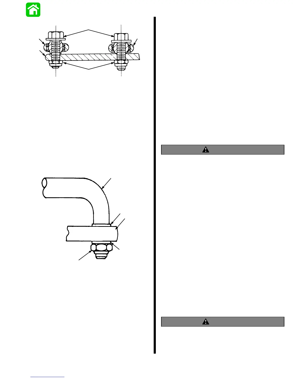
a - Engine Steering Arm
b - Steering Link Rod
c - Steering Eye and Coupler
d - Pivot Bolts - Torque to 20 lbs. ft. (27.1 Nm)
e - Locknuts - Torque to 20 lbs. ft. (27.1 Nm)
Figure 7. Steering Link Rod and Steering Eye
with Coupler Installed on Engine
Steering Arm
7. Lubricate hole(s) in end of steering cable(s) with
Quicksilver 2-4-C w/Teflon and assemble steering
link rod(s) to steering cable end, as shown in Fig-
ure 8. Tighten self-locking nut until it seats [DO
NOT exceed 120 lbs. in. (13.5 Nm)], then back
nut off 1/4-turn.
a
b
c
d
b
a - Steering Link Rod
b - Flat Washer (5/8” O.D.)
c - Steering Cable End
d - Locknut; Tighten Until it Seats [DO NOT Exceed 120 lbs. in.
(13.5 Nm)], then Back Nut Off 1/4-Turn.
Figure 8. Steering Link Rod Assembled on
Steering Cable
Steering Eyes and Coupler Installation
1. Position engines so that they are facing straight
forward. (Distance between centers of threaded
pivot bolt holes in engine steering arms must be
equal to distance between propeller shaft
centers.)
2. Lubricate inside of rubber sleeves (Figure 9) and
slide onto coupler.
3. Slide rubber bushings (Figure 9) onto steering
eyes.
4. Thread steering eyes (Figures 9 and 10) into cou-
pler and adjust steering eyes so that distance be-
tween centers of pivot bolt holes in steering eyes
is the same distance as between centers of
threaded pivot holes in engine steering arms. Ex-
posed steering eye threads should be equal at
both ends of coupler and must not extend out of
coupler more than 2-3/4″ (70mm).
WARNING
Both steering eyes must be threaded into coupler
3/4″ (19mm) minimum. Thread length of steering
eye is 3-1/2″ (89mm), so exposed thread must not
extend out of coupler more than 2-3/4″. Failure to
adhere to this requirement could result in steering
system failure.
5. Lubricate steering eye threads, pivot bolts, and
ball joints with Quicksilver Anti-Corrosion Grease
(92-78376-12) before assembling.
6. Assemble steering eyes and coupler to top side,
front holes of steering arm with pivot bolts and
locknuts, as shown in Figures 7 and 10.
IMPORTANT: With steering eyes and coupler
installed and before tightening pivot bolts, check
engine alignment. Distance between pivot bolts
centers and distance between propeller shaft
centers must be equal for proper steering. If ad-
justment is necessary, remove pivot bolt from one
steering eye and turn eye in or out to correct align-
ment. Both steering eyes MUST BE threaded into
coupler 3/4″ (19mm) minimum.
7. Torque pivot bolts to 20 lbs. ft. (27.1 Nm), then
thread self-locking nut (Figure 7) onto bolts and
torque nuts to 20 lbs. ft. (27.1 Nm).
WARNING
Both steering eyes MUST BE threaded into
coupler 3/4″ minimum, and jam nut (Figure 9) must
be secured against coupler to prevent coupler
from turning. Torque jam nut to 20 lbs. ft.