2. Electrical Connections
2.2 Electrical Connections for
a Feeder Track
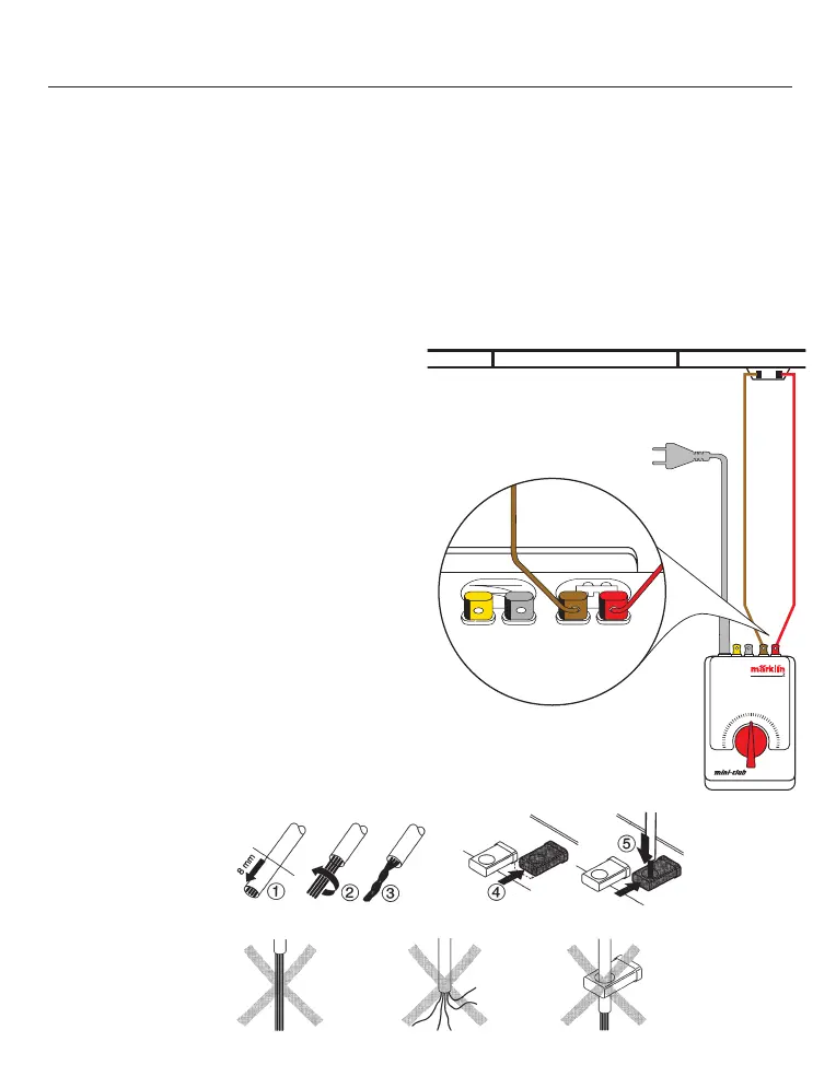
Important! The feeder wires from the
layout to the transformer must never be
plugged into a household power outlet.
Make sure your children are aware of
this danger!
1. Strip a small amount of insulation from
the ends of the red and brown feeder
wires, that are included with the 8590 fee-
der track, and connect each of these to
the terminal of the same color on the
power pack. The red wire is connected
to feeder track’s terminal clip that is
connected to the rail closest to the power
pack. The brown wire is connected to the
other terminal clip on the feeder track. In
the diagram below the feeder track as
installed shows the brown wire connected
to the left terminal clip and the red wire
connected to the right terminal clip of the
feeder track.
What is the purpose of this requirement
that the beginner may find somewhat con-
fusing?
If you adhere to this requirement, then a
locomotive will always travel to the right
Preparing the wire
and connecting it
Pay attention
to the following
in the process
when the speed control knob is turned to
the right from the center position. If the
speed control knob is turned to the left,
then the locomotive will correspondingly
travel to the left. If the red and brown wires
are reversed, then the locomotive’s direc-
tion of travel will no longer agree with the
direction in which the speed controller is
turned on the power pack.
21
 Loading...