EasyManuals Logo

Masibus LC5248E-AT User Manual

Masibus LC5248E-AT
44 pages
To Next Page IconTo Next Page
To Previous Page IconTo Previous Page
Page #33 background imageLoading...
Page #33 background image
Model: LC5296-AT /LC5248E-AT/LC5296V-AT masibus
Doc. Ref. no. : - m61C/om/301
Issue no. 13
User’s Manual Page 33 of 44
8. ALARM OUTPUT
For all Alarm outputs there are five settings. (As shown in configuration mode Menu)
Set Value (in run mode)
Type
Hysteresis(Dead band)
Direction (Normal/Fail safe)
Delay
SET VALUE: Alarm set point
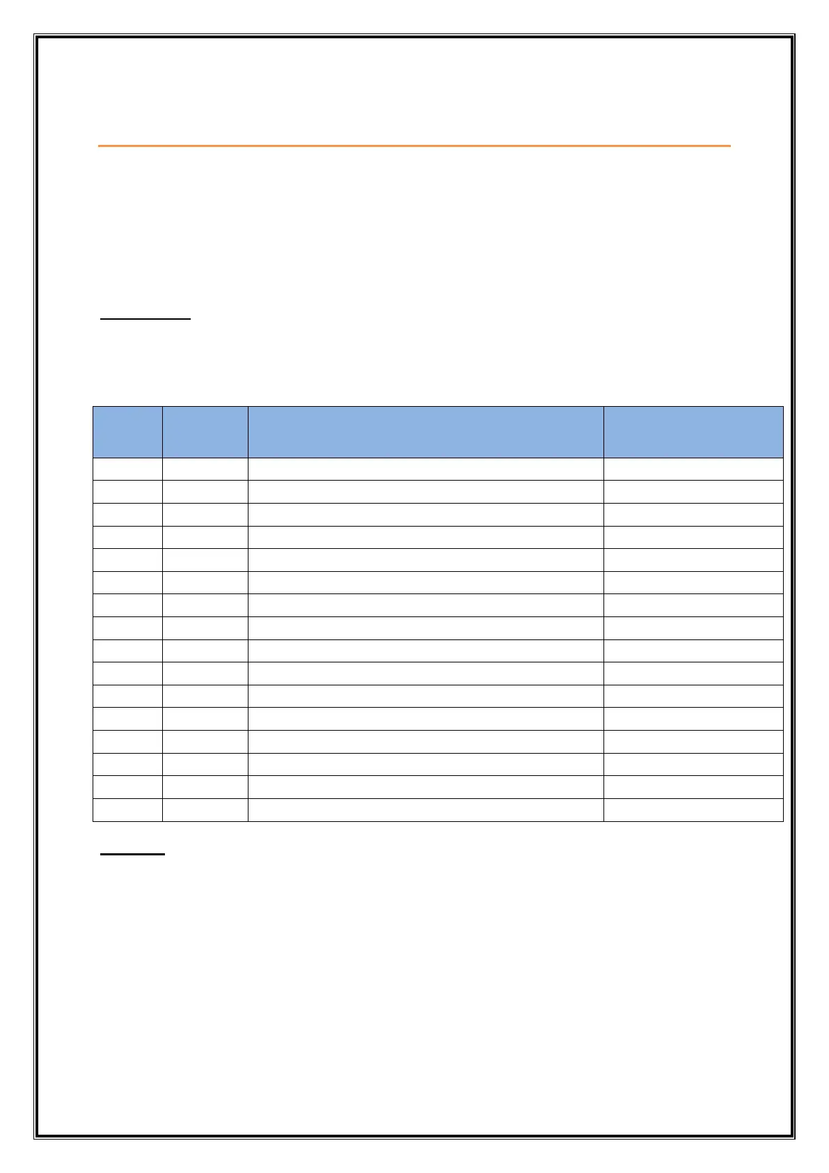
8.1 ALARM TYPES
Various alarm operations are shown in the reference figure.
ALARM
TYPE
NO
Display
message
ALARM TYPE
Note
0
none
None
NO operation available
1
Pv.d.H
Deviation High alarm
Ref figure 3
2
Pv.d.l
Deviation Low alarm
Ref figure 4
3
Pv.d.r
Deviation High & Low range alarm
Ref figure 5
4
Pv.d.b
Deviation High & Low Band alarm
Ref figure 6
5
Pv.a.H
Absolute value High alarm
Ref figure 1
6
Pv.A.L
Absolute value Low alarm
Ref figure 2
7
SP.A.H
Absolute value set point high alarm
Ref figure 7
8
SP.A.L
Absolute value set point low alarm
Ref figure 8
9
P.S.d.H
Deviation High alarm with standby
Same as figure 3
10
P.S.d.L
Deviation Low alarm with standby
Same as figure 4
11
P.S.d.r
Deviation High & Low range alarm with standby
Same as figure 5
12
P.S.d.b
Deviation High & Low limit alarm with standby
Same as figure 6
13
P.S.A.H
Absolute value High alarm with standby
Same as figure 1
14
P.S.A.L
Absolute value Low alarm with standby
Same as figure 2
15
PV.-E.
PV error(OPEN/OVER/UNDER)
Note 1
NOTE-1:
The fault diagnosis output turns on in case of input burnout (PV) failure.

Questions and Answers:

Question and Answer IconNeed help?

Do you have a question about the Masibus LC5248E-AT and is the answer not in the manual?

Masibus LC5248E-AT Specifications

General IconGeneral
BrandMasibus
ModelLC5248E-AT
CategoryController
LanguageEnglish

Related product manuals