MLI Ultra 12/2750, 12/5500, 24/5500 – User and Installation Manual
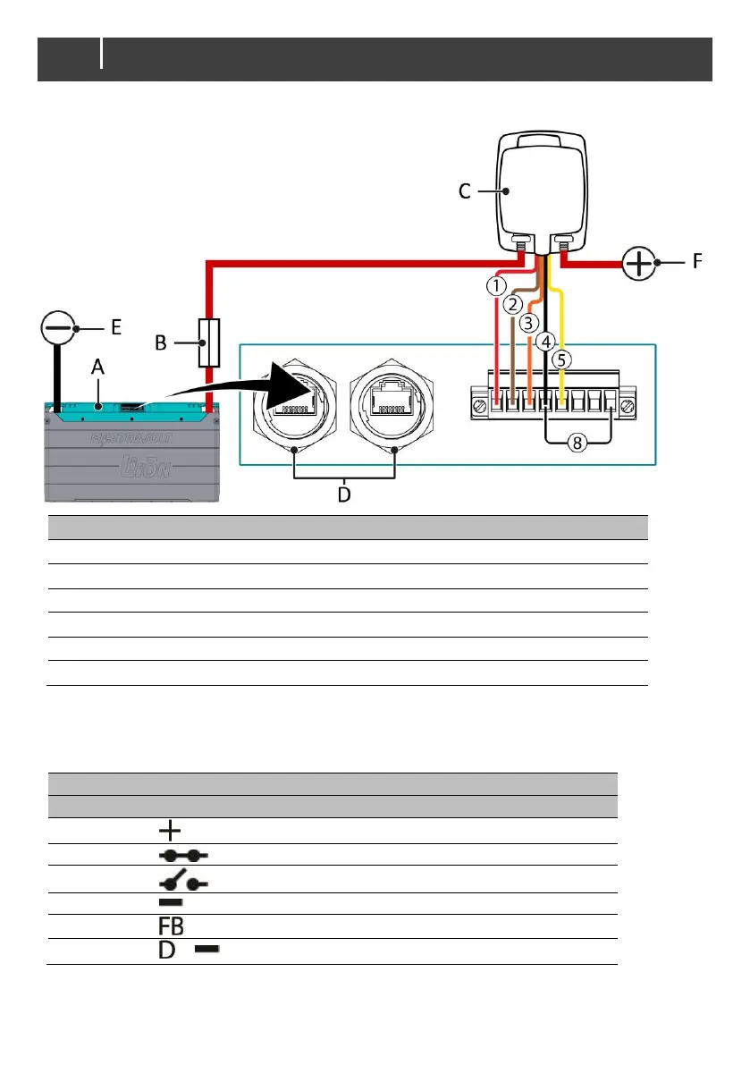
Installation drawing of a single unit
Battery fuse in positive cable
MasterBus / CZone connection (see sections Network wiring on pages 16 and 24)
Note: for safety reasons, the jumper wire is intentionally factory-set on pins 4 and 5, to generate an
alarm and as a reminder to install the relay. To void the alarm: wire the relay and move the
jumper wire to pins 4 and 8.
Relay Control (RC) positive
Relays connector detect, connect to RC minus
 Loading...