MLI Ultra 12/2750, 12/5500, 24/5500 – User and Installation Manual
Installation procedure for a single unit
WARNING!
Always comply with all local rules and regulations.
WARNING!
Do not use a sensor for temperature compensated charging. Temperatures of the
battery and its cells are monitored by the built-in BMS.
1. Switch off all loads and chargers.
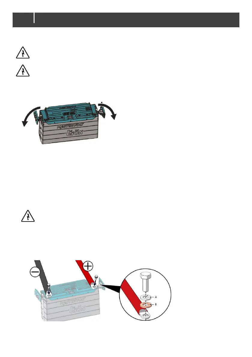
2. Extract the side handles to uncover the battery terminals.
3. Integrate a fuse holder in the positive battery wire but do not place the fuse yet.
4. Set the safety relay knob to “LOCK OFF”, see page 11.
5. Integrate the safety relay in the positive battery wire.
Disconnect the battery safety connector, item (6) in figure Main Parts on page 7, by loosening
its screws. Connect the wires of the safety relay onto the battery safety connector as shown in
the installation diagram on page 10 (see also chapter 15 in case of multiple units connection).
Replace the battery safety connector and fasten with the screws. Please note that if the wiring
is not properly fastened, the safety relay will open.
6. Connect the DC main wiring, positive to +, negative to -.
WARNING!
In installations with a negative earth: Connect the negative cable last of all to prevent
short circuiting.
Note: Use properly sized and reliable cables, cable lugs and battery terminals. Tighten all
connections. For the main DC connections use 14.7 to 19.6 Nm / 130 to 170 InLbs torque.
See the illustration detail for the right order of placing the spring washer (A) and the flat
washer (B).
7. Close the side handles to cover the battery terminals again.
8. Connect the MasterBus/CZone cabling, see page 16/24.
9. Continue with the commissioning procedure, see next chapter.
 Loading...