MLI Ultra 12/2750, 12/5500, 24/5500 – User and Installation Manual
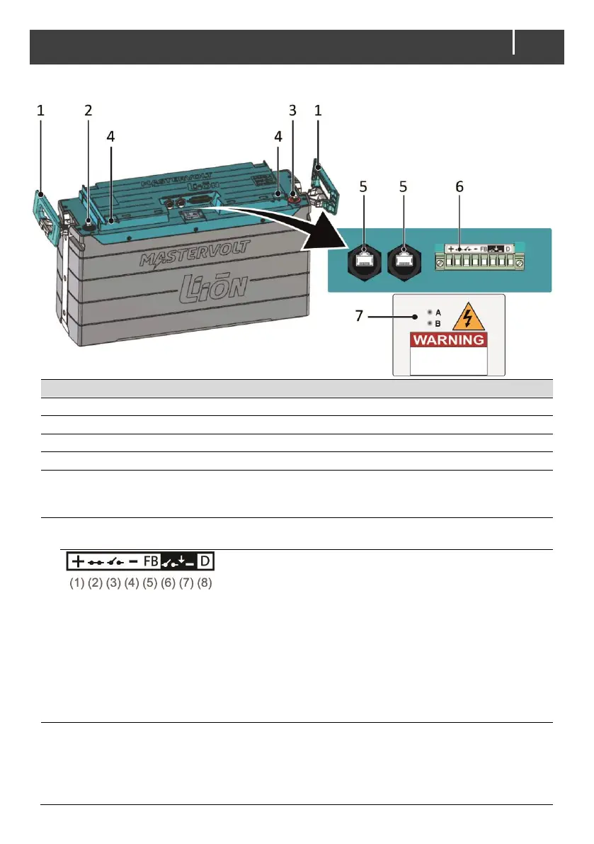
Extractable side handle for lifting
Negative battery terminal (M8 /
5
/
16
")
Positive battery terminal (M8 /
5
/
16
")
MasterBus / CZone connection (see sections Network wiring on pages 16 and 24)
When waterproof protection is required, Mastervolt can also supply waterproof cable
glands.
Battery Safety connector, see the Installation drawing on page 10 (single), 32 (parallel) or
33 (series)
(1) Relay Control (RC) positive (12/24V)
(2) Close relay pulse (12/24V)
(3) Open relay pulse (12/24V)
(4) RC minus (12/24V)
(5) FeedBack signal relay
(6) RC open relay from other battery
(7) RC minus from other battery
(8) Relay connector detect (connect to RC minus)
DIP switch cover and LED indicators
A (red): on indicates an unrecoverable error; contact your Mastervolt supplier.
B (yellow): 1 short blink, long pause; a low State of Charge;
2 short blinks, long pause; CZone identification in progress;
Steady blinking; firmware update in progress.
 Loading...