Matrix SATATYA Devices Manual 41
Connecting the Device
All wiring as described in this section should comply with the applicable local wiring regulations.
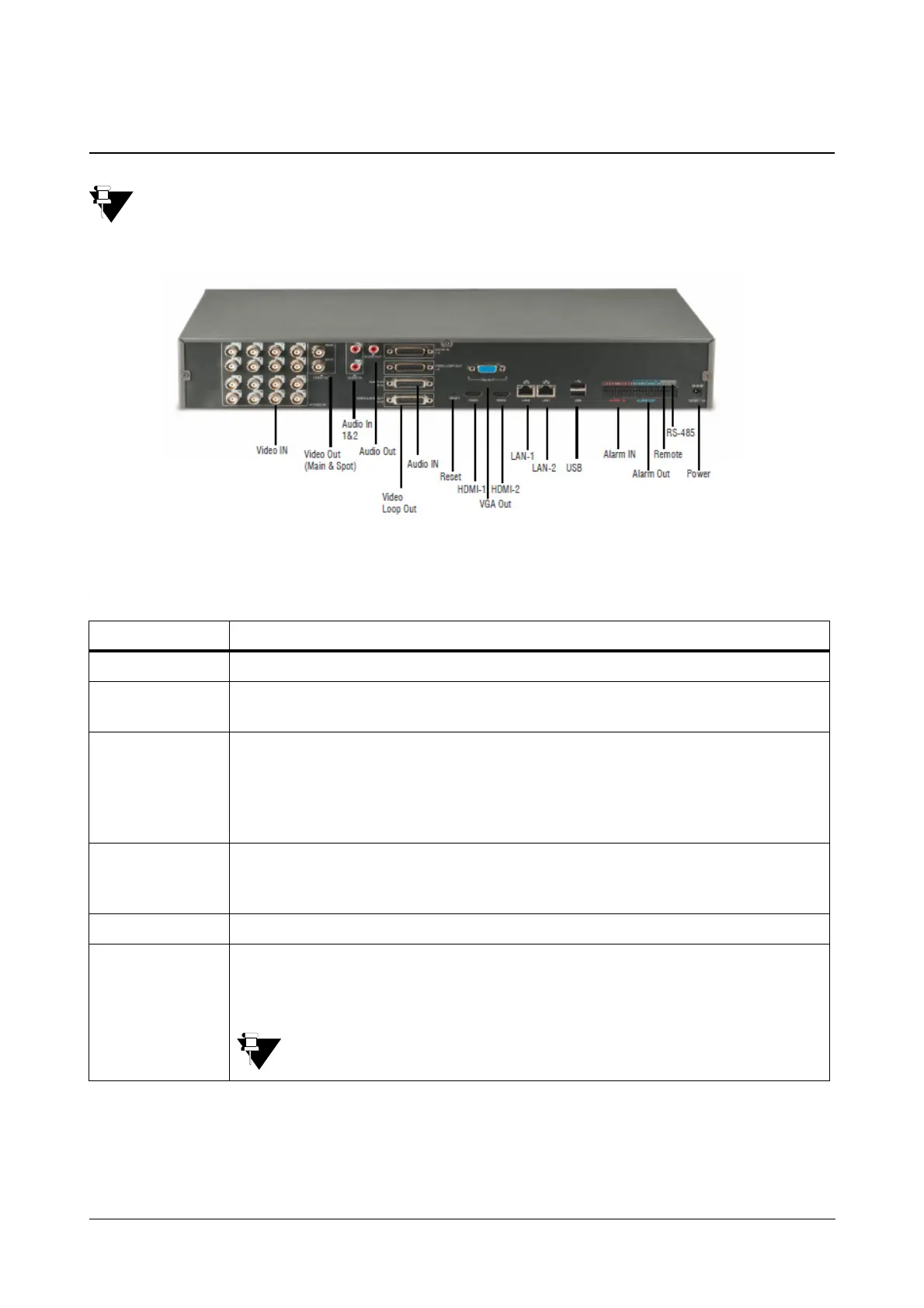
The above figure displays the connectors on the rear face of the SATATYA HVR1624P. For the availability of
connectors in other devices, see Ports and Connectors in See “System Architecture” on page 10.
Connectors Description
DC 12V Apply 12 VDC using a DC switching adapter.
Alarm Sensor
Inputs
Connect the external sensor devices to signal the SATATYA NVR,HVR to react to the
events. For details See “Hooking up Inputs” on page 81.
Sensor Outputs
An internal relay connects/closes the two connected external sensor output terminals. The
relay can be triggered to close the two sensor connections by either motion or a sensor
input, if enabled in the Device I/O Settings. This can be used to turn on or off an external
buzzer or light. When using the Relay outputs, ensure the voltage/current capacity of the
relays are not exceeded.
Remote IR
receiver
In the event of placing the device display away from the device NVR/HVR, the installer can
connect a remote IR receiver to access the SATATYA device controls. Connect the three
conductors from a remote IR receiver unit to the appropriate terminals.
Ethernet Connect the LAN cables to the RJ -45 jack connectors
HDMI Ports
This is provided to connect HDMI displays to the SATATYA device if required. One
connector (HDMI 1) is used as the main video output with local video display and menu
operations. And other connector (HDMI 2) is used for Spot video Output.
In this manual, the “Local Client” has been used to term HDMI (video) Out.
 Loading...