19
T50/T100 PTM – User Guide – Version 2 Issue 1
Installation – Installing a Photocell
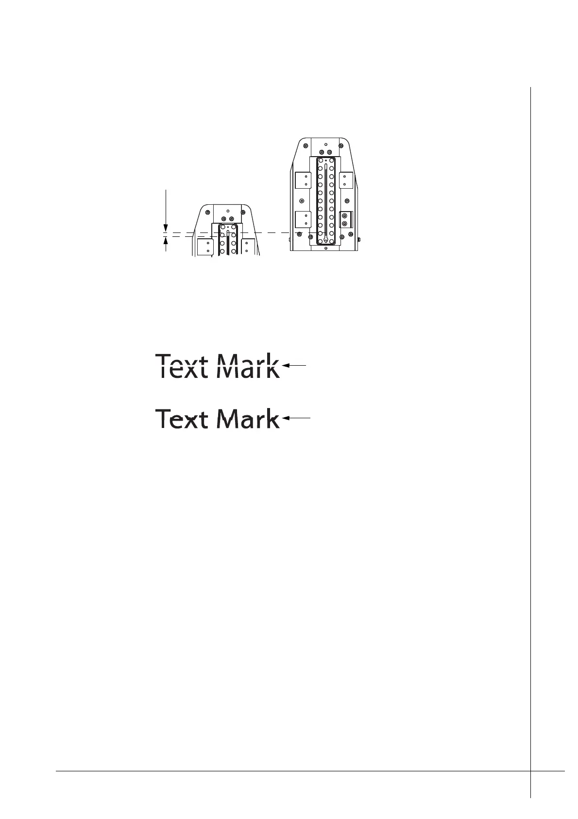
below. The distance between the nozzles must be 0,13 mm apart.
Figure 16 - Vertical nozzle adjustment
If the print heads are placed to far apart, greater than 0,13 mm, the mark will have a white
gap. If they are too close together the mark will overlap, as shown below.
Figure 17 - Incorrect vertical spacing
It can be difficult to obtain the precise distance of 0,13 mm between the two heads. A visual
inspection of a number of print tests in relation to fine adjustments is often enough to ensure
the print heads are satisfactorily adjusted. In such cases there may well exist a slight error in
the actual distance but the printout looks fine.
Installing a Photocell
A photocell detects an approaching print target and signals that a printout should be made. A
photocell can be ordered from Matthews if required and is easily attached to the side of the
print head, as shown in Figure 6 on page 10.
The photocell must be positioned so that it is upstream of the print head, so that the print
target passes in front of it first, before passing the print head nozzles. If more than one print
head is used, stacked installations, the photocell must be positioned on the first print head that
the print target will pass in front of.
The photocell must be connected to the DSUB connection that is labeled PHOTOCELL on
the back of the print head.
Once a photocell is connected it will be listed in the Configuration menu of the PCM. Further
information regarding configuration can be found in the Technical Manual for the PCM.
Bottom print head
Bottom print head
White gap caused by print
heads being to far apart
Overlapping text due to print
heads being to close together