Installation – Commissioning a T50/T100 PTM
T50/T100 PTM – User Guide – Version 2 Issue 1
22
Caution: Failure to open the Ink-Vent-Screw will lead to print failure or damage to
the print head. Make sure it is open!
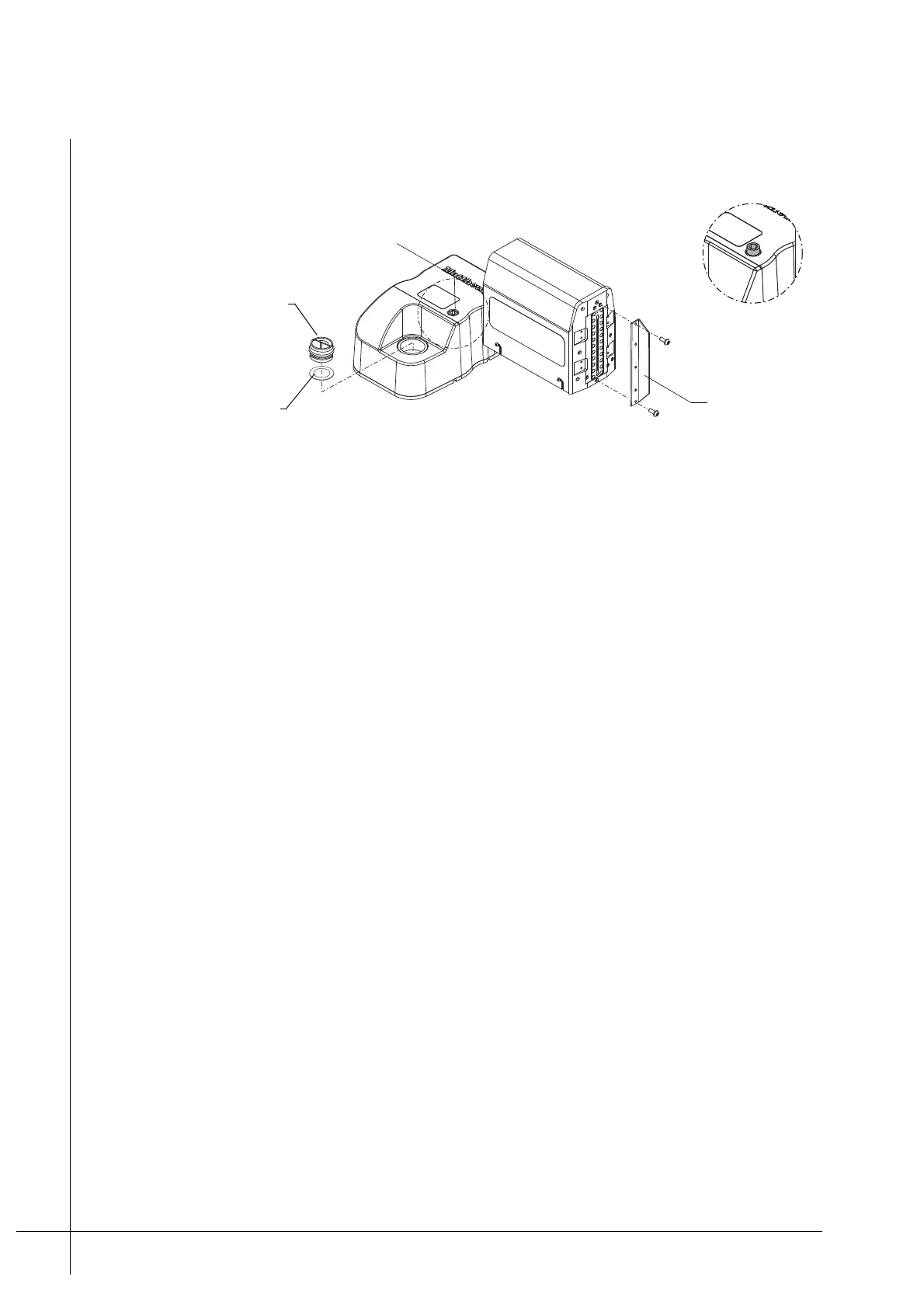
Figure 20 - Nozzle-Protector-Plate
3. Unscrew and remove the Nozzle-Protector-Plate from the front of the print head, as
shown above. Store it in a clean place for future use.
4. Unscrew and remove the Ink-Reservoir-Cap from the Ink-Inlet. Store it in a clean place
for future use.
5. Make sure that the Ink-Inlet-Seal, inside the Ink-Inlet, is clean and correctly seated.
6. Put a new Ink-Bottle into the Ink-Inlet as described under “Ink-Bottle Replacement” on
page 28.
7. Connect an encoder/photocell to the back of the print head, as required.
8. Connect the print head(s) to the RJ-45 connector that ia labelled "Printer Network" on
the PCM’s interface panel. A single print head can either be connected directly or via a
dedicated Viacode Ethernet switch.
If more than one print head is installed, they must be connected to a dedicated Viacode
Ethernet switch first, which in turn is connected to the PCM.
9. Connect the print head’s Power-Supply-Pack to the DSUB connection that is labelled
Power on the back of the print head. Connect the Power-Supply-Cable between the
Power-Supply-Pack and a mains outlet supply. Make sure that the correct power is
supplied to the print head.
Note: The Power-Supply-Pack and the Power-Supply-Cable are sold separately to the
PTM.
10. Wait until the READY LED on the back of the print head illuminates green.
Note: The READY LED will illuminate green when the print head has reached the correct
operating temperature, which takes approximately two minutes. It will illuminate orange
while warming up.
Ink-Reservoir-Cap
Ink-Vent-Screw
Nozzle-
Protector-Plate
Detail A
A
Ink-Inlet-Seal
A