Comet Executive Gas Installation
2-13
WARNING
Only qualied personnel
should make the gas
connections to the unit.
Improper installation could
result in serious injury.
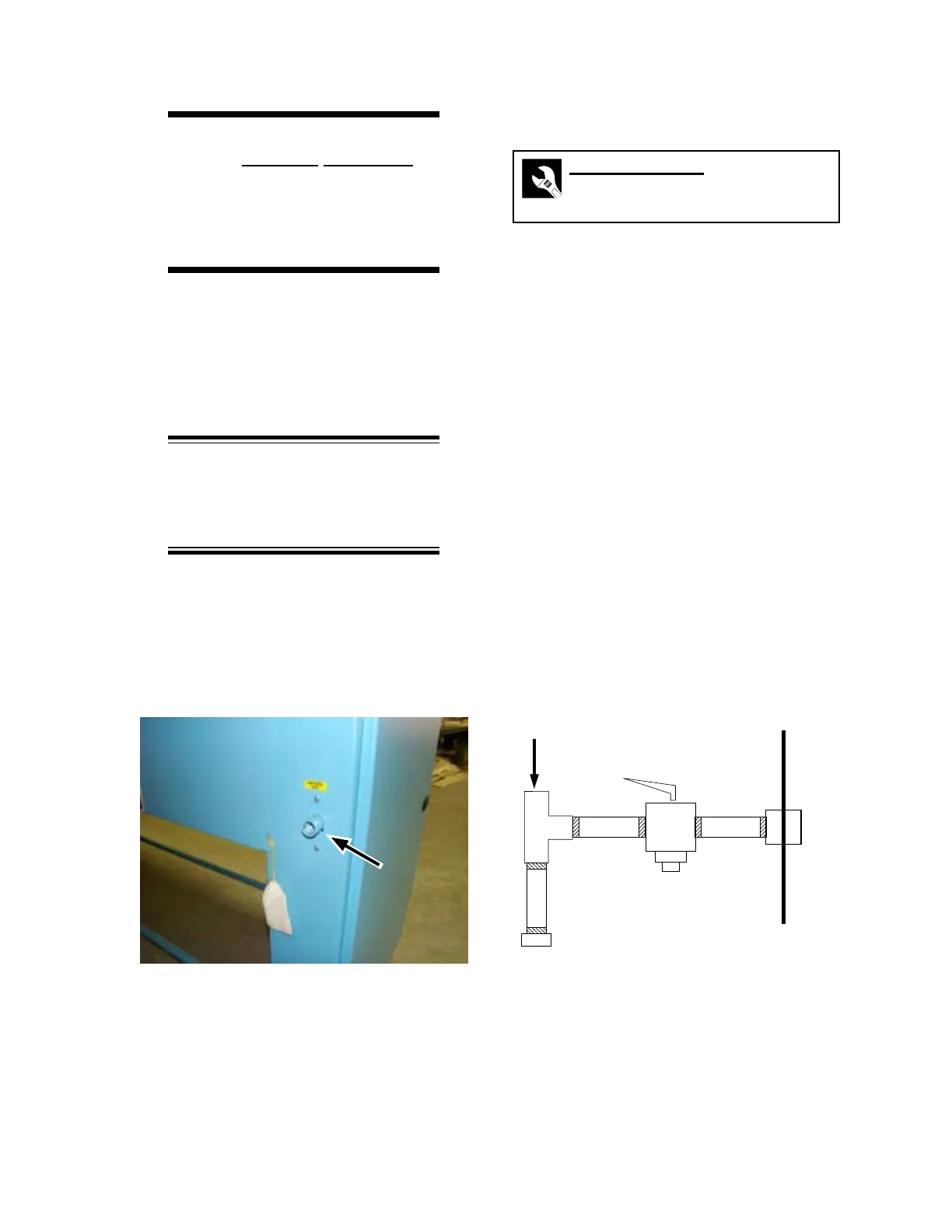
The gas connection to the unit is made at the
back of the left endframe. A 1/2” (DN 15) gas inlet
connection (Figure 2-13) is provided to connect
the incoming gas line. A manual gas shut-o
valve is supplied with the unit. Other components
must be locally supplied.
NOTE: Pipe thread compound is
required on all gas line connections
to ensure a leakproof installation.
Comply with local codes.
Figure 2-13: The 1/2” gas supply connection is at
the rear of the left endframe.
Figure 2-14: Install the hardware for the gas
connection as shown.
ABC
D
E
F
Rear
Gas Cock
Shut-O Valve Installation
Required Tools
Pipe thread compound
Pipe wrench
The gas line to the unit should be routed so it
does not interfere with any service panel or block
access to the back of the unit.
1. Check all internal gas connections in the
unit. Tighten any unions that became loose
during shipment.
2. Connect a short nipple (Figure 2-14, A)
to the coupling at the back of the left
endframe (Figure 2-13).
3. Connect the gas shut-o valve (Figure
2-14, B) to the short nipple (A). Make
sure that the arrow is neither upside down
nor vertical.
4. Connect a short nipple (C) to the other side
of the gas shut-o valve (B).
5. Connect the branch of a tee (D) to the
other side of the nipple (C). Install the tee
vertically.