Motherboard Design Guide
Requirements for Components of Third-party Suppliers
maxon motor control
ESCON Servo Controller Document ID: rel4734
5-33
ESCON Module 50/5 Hardware Reference Edition: November 2014
© 2014 maxon motor. Subject to change without prior notice.
5.1.3 Motor Cables/Motor Chokes
The ESCON Module 50/5 is not equipped with internal motor chokes.
The majority of motors and applications do not require additional chokes. However, in the case of high
supply voltage with very low terminal inductance, the ripple of the motor current can reach an
unacceptably high value. This causes the motor to heat up unnecessarily and causes instable control
behavior. The minimum terminal inductance required per phase can be calculated using the following
formula:
If the result of the calculation is negative, no additional chokes are necessary. Nevertheless, the use of
chokes in combination with additional filter components can be useful to reduce the emission of electro-
magnetic interference.
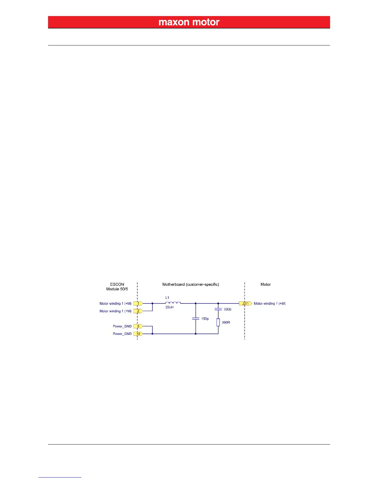
An additional choke must feature electromagnetic shielding, a high saturation current, minimal losses,
and a nominal current greater than the continuous current of the motor. The below wiring example
refers to an additional inductance of 22 μH. If a different additional inductance is required, also the filter
components must be adapted accordingly. Should you need further help with the filter design, contact
maxon Support at http://support.maxonmotor.com.
Figure 5-24 Wiring of Motor Winding 1 (analogously valid also for Motor Windings 2 & 3)
Additional external inductance per phase
Operating voltage +V
CC
Switching frequency of the power stage = 53 600 Hz
Nominal current of the motor (line 6 in the maxon catalog)
Terminal inductance of the motor (line 11 in the maxon catalog)