Setup
Status Indicators
maxon motor control
3-24 Document ID: rel4734 ESCON Servo Controller
Edition: November 2014 ESCON Module 50/5 Hardware Reference
© 2014 maxon motor. Subject to change without prior notice.
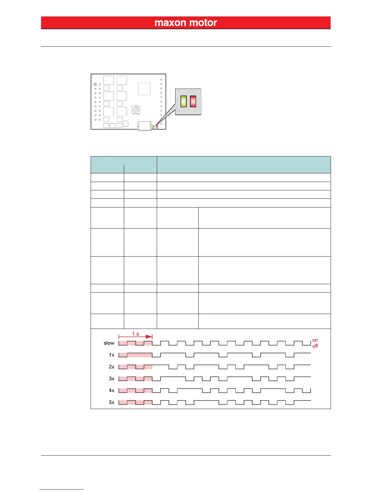
3.5 Status Indicators
Light-emitting diodes (LEDs) indicate the actual operating status (green) and possible errors (red).
Figure 3-16 LEDs – Location
Table 3-10 LEDs – Interpretation of Condition
LED
Status/Error
Green Red
off off INIT
slow off DISABLE
on off ENABLE
2x off STOPPING; STOP STANDSTILL
off 1x ERROR
• +Vcc Overvoltage Error
• +Vcc Undervoltage Error
• +5 VDC Undervoltage Error
off 2x ERROR
• Thermal Overload Error
• Overcurrent Error
• Power Stage Protection Error
• Internal Hardware Error
off 3x ERROR
• Encoder Cable Break Error
• Encoder Polarity Error
• DC Tacho Cable Break Error
• DC Tacho Polarity Error
off 4x ERROR • PWM Set Value Input out of Range Error
off 5x ERROR
• Hall Sensor Pattern Error
• Hall Sensor Sequence Error
• Hall Sensor Frequency too high Error
off on ERROR
• Auto Tuning Identification Error
• Internal Software Error