Motherboard Design Guide
ESCON Module Motherboard (438779)
maxon motor control
5-42 Document ID: rel4734 ESCON Servo Controller
Edition: November 2014 ESCON Module 50/5 Hardware Reference
© 2014 maxon motor. Subject to change without prior notice.
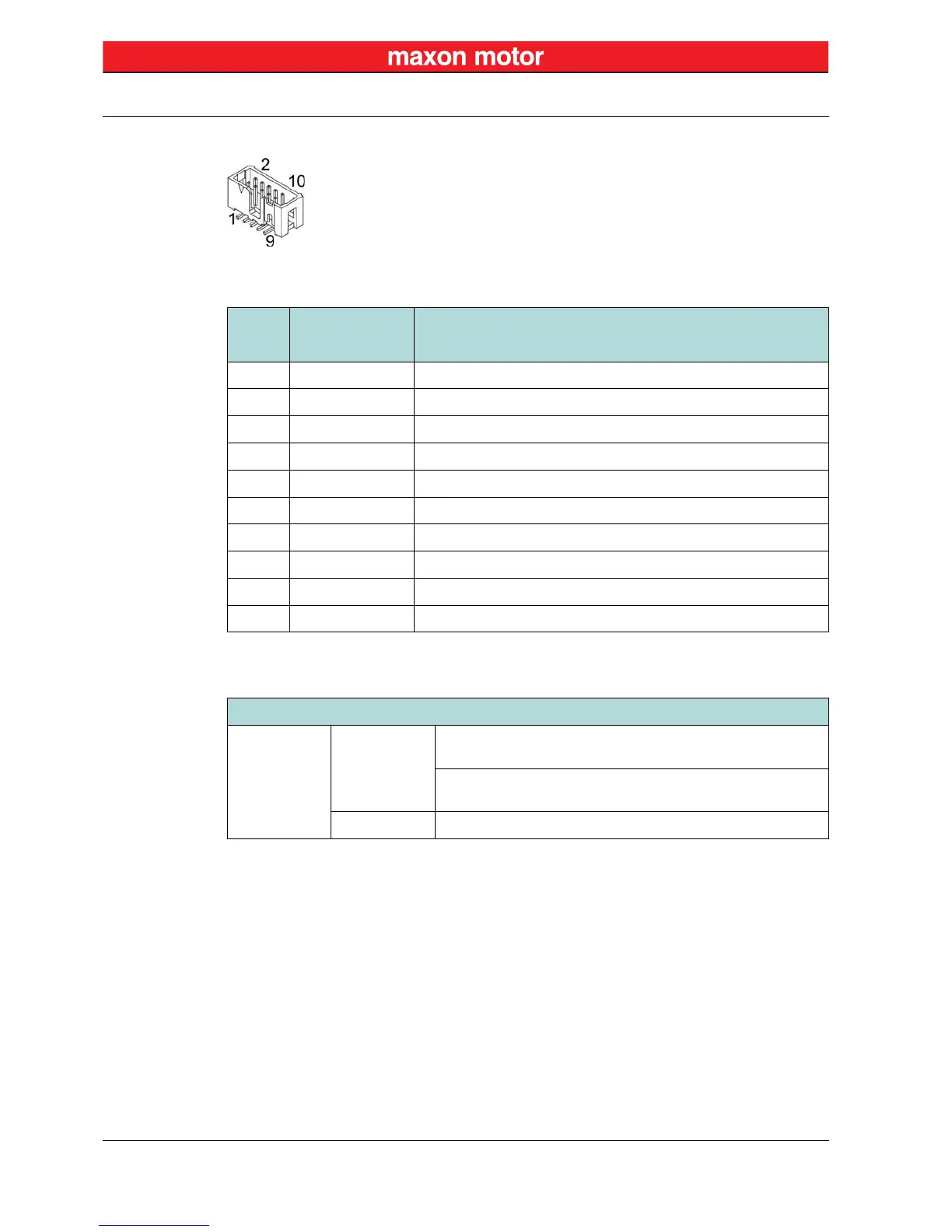
5.7.2.4 Encoder (J4)
Figure 5-32 ESCON Module MoBo – Encoder Socket J4
Table 5-21 ESCON Module MoBo – Encoder Socket J4 – Pin Assignment
Table 5-22 ESCON Module MoBo – Encoder Socket J4 – Accessories
J4
Signal Description
Pin
1 not connected –
2 +5 VDC Encoder supply voltage (+5 VDC;
≤70 mA)
3 GND Ground
4 not connected –
5 Channel A\ Channel A complement
6 Channel A Channel A
7 Channel B\ Channel B complement
8 Channel B Channel B
9 not connected –
10 not connected –
Accessories
Suitable strain
relief
Retainer
For sockets with strain relief:
1 retainer clip, height 13.5 mm, 3M (3505-8110)
For sockets without strain relief:
1 retainer clip, height 7.9 mm, 3M (3505-8010)
Latch For sockets with strain relief: 2 pieces, 3M (3505-33B)


 To Next Page