Setup
Connections
maxon motor control
ESCON Servo Controller Document ID: rel4734
3-13
ESCON Module 50/5 Hardware Reference Edition: November 2014
© 2014 maxon motor. Subject to change without prior notice.
3.3 Connections
The actual connection will depend on the overall configuration of your drive system and the type of
motor you will be using.
Follow the description in the given order and choose the wiring diagram that best suits the components
you are using. For corresponding wiring diagrams Chapter “4 Wiring” on page 4-25.
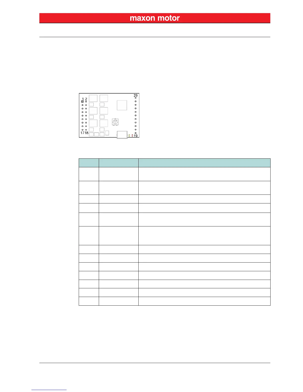
3.3.1 Pin Assignment
Figure 3-2 Pin Assignment
Table 3-6 Pin Assignment (Pins 1-18)
Pin Signal Description
1/2
Motor (+M)
Motor winding 1
DC motor: Motor +
EC motor: Winding 1
3/4
Motor (–M)
Motor winding 2
DC motor: Motor –
EC motor: Winding 2
5/6 Motor winding 3 EC motor: Winding 3
7/8
+V
CC
Nominal operating voltage (+10…+50 VDC)
9/10
Power_GND
GND
Ground of operating voltage
Ground
11 +5 VDC
Hall sensor supply voltage (+5 VDC; ≤30 mA)
Encoder supply voltage (+5 VDC; ≤70 mA)
Auxiliary output voltage (+5 VDC; ≤10 mA)
12 Channel A Encoder channel A
13 Hall sensor 1 Hall sensor 1 input
14 Channel A\ Encoder channel A complement
15 Hall sensor 2 Hall sensor 2 input
16 Channel B Encoder channel B
17 Hall sensor 3 Hall sensor 3 input
18 Channel B\ Encoder channel B complement