Motherboard Design Guide
ESCON Module Motherboard (438779)
maxon motor control
ESCON Servo Controller Document ID: rel4734
5-39
ESCON Module 50/5 Hardware Reference Edition: November 2014
© 2014 maxon motor. Subject to change without prior notice.
5.7.2 Connections
Note
The USB interface is located directly at the ESCON Module 50/5.
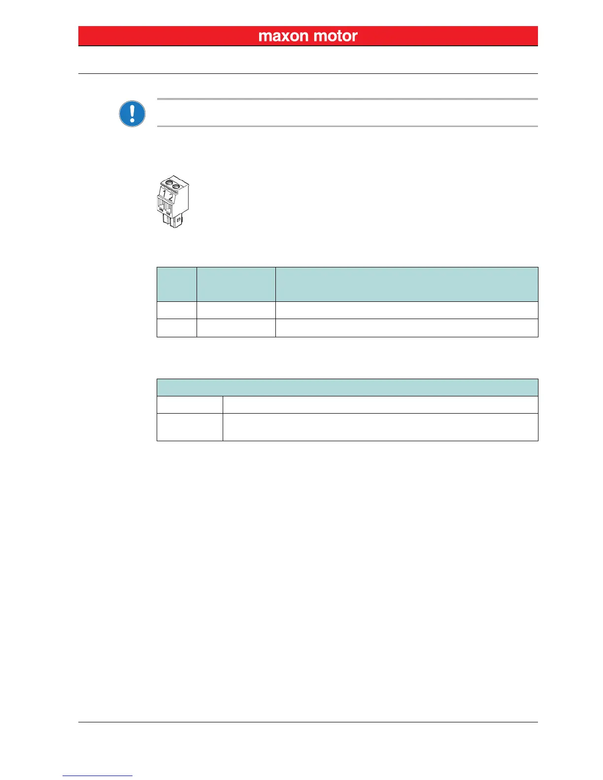
5.7.2.1 Power Supply (J1)
Figure 5-29 ESCON Module MoBo – Power Plug J1
Table 5-14 ESCON Module MoBo – Power Plug J1 – Pin Assignment
Table 5-15 ESCON Module MoBo – Power Plug J1 – Specification & Accessories
J1
Signal Description
Pin
1 Power_GND Ground of operating voltage
2
+V
CC
Nominal operating voltage (+10…+50 VDC)
Specification / Accessories
Type Pluggable screw-type terminal block, 2 poles, 3.5 mm pitch
Suitable cables
0.14…1.5 mm
2
multi-core, AWG 28-14
0.14…1.5 mm
2
single wire, AWG 28-14