Motherboard Design Guide
Requirements for Components of Third-party Suppliers
maxon motor control
5-32 Document ID: rel4734 ESCON Servo Controller
Edition: November 2014 ESCON Module 50/5 Hardware Reference
© 2014 maxon motor. Subject to change without prior notice.
5.1 Requirements for Components of Third-party Suppliers
5.1.1 Socket Headers
The ESCON Module 50/5’s implementation with pin headers permits mounting in two different ways.
The module can either be plugged onto a socket header (Table 5-11) or be directly soldered to a
printed circuit board.
5.1.2 Supply Voltage
To protect the ESCON Module 50/5, we recommend using an external circuit breaker, a TVS diode, and
a capacitor in the voltage supply cable. In this regard, please note the following recommendations:
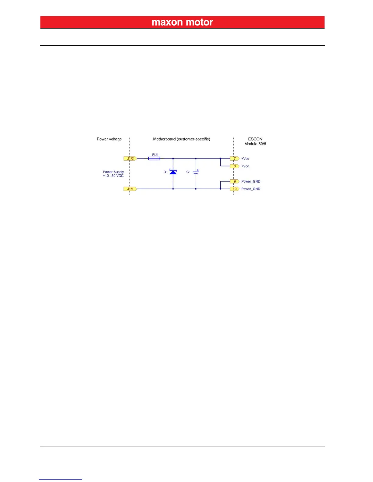
Figure 5-23 Wiring of Voltage Supply Cable
I
NPUT FUSE (FU1)
An input fuse (FU1) is necessary in order to provide reverse polarity protection. Together with an unipo-
lar TVS diode (D1), this prevents current from flowing in the wrong direction.
TVS D
IODE (D1)
To protect against overvoltage resulting from voltage transients or brake energy feedback, we recom-
mend connecting a TVS (transient voltage suppressor) diode (D1) to the voltage supply cable.
C
APACITOR (C1)
The function of the ESCON Module 50/5 does not necessarily require the use of an external capacitor
(C1). To further reduce voltage ripple and feedback currents, an electrolytic capacitor can be connected
to the voltage supply cable.