Motherboard Design Guide
ESCON Module Motherboard (438779)
maxon motor control
ESCON Servo Controller Document ID: rel4734
5-45
ESCON Module 50/5 Hardware Reference Edition: November 2014
© 2014 maxon motor. Subject to change without prior notice.
5.7.2.6 Analog I/Os (J6)
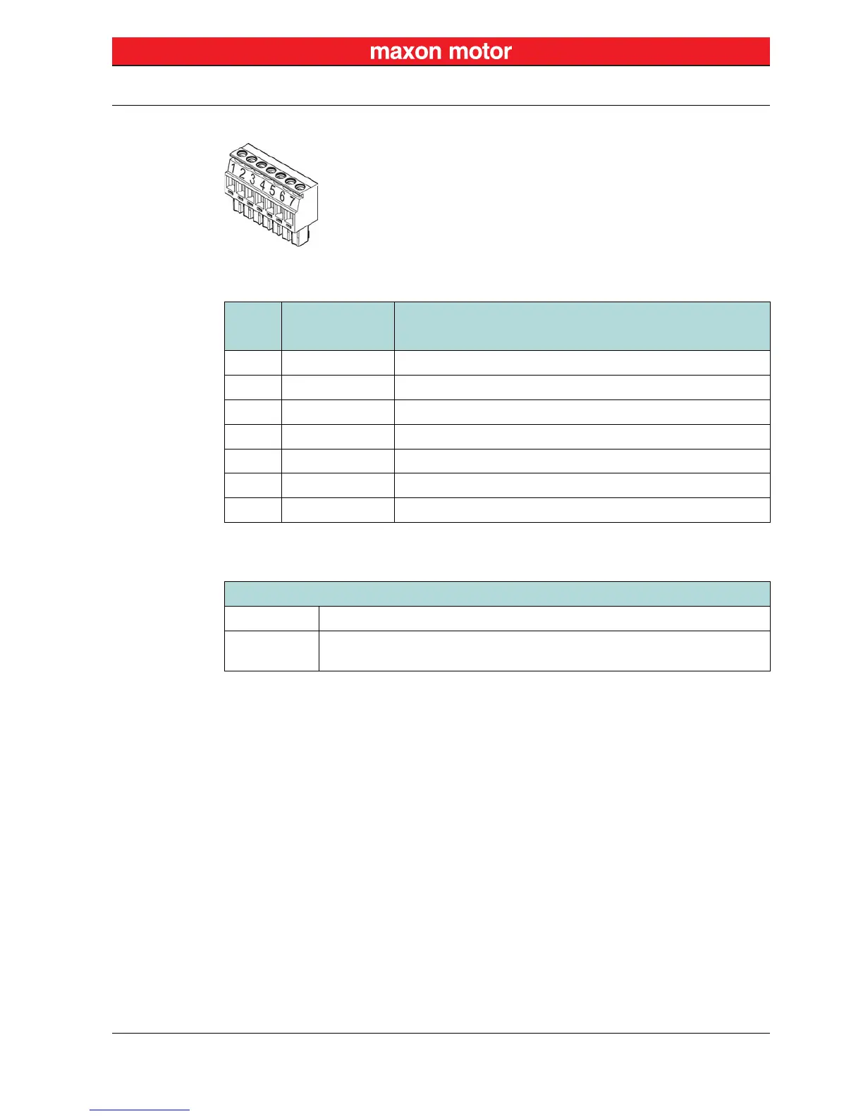
Figure 5-34 ESCON Module MoBo – Analog I/Os Plug J6
Table 5-26 ESCON Module MoBo – Analog I/Os Plug J6 – Pin Assignment
Table 5-27 ESCON Module MoBo – Analog I/Os Plug J6 – Specification & Accessories
J6
Signal Description
Pin
1 AnIN1+ Analog input 1, positive signal
2 AnIN1– Analog input 1, negative signal
3 AnIN2+ Analog input 2, positive signal
4 AnIN2– Analog input 2, negative signal
5 AnOUT1 Analog output 1
6 AnOUT2 Analog output 2
7 GND Ground
Specification / Accessories
Type Pluggable screw-type terminal block, 7 poles, 3.5 mm pitch
Suitable cables
0.14…1.5 mm
2
multi-core, AWG 28-14
0.14…1.5 mm
2
single wire, AWG 28-14