maxon motor control
ESCON Servo Controller Document ID: rel4734
Z-53
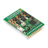
ESCON Module 50/5 Hardware Reference Edition: November 2014
© 2014 maxon motor. Subject to change without prior notice.
A
additionally applicable regulations 5
analog inputs
21
applicable EU directive
11
assignment of the connections
13
C
cables (prefab)
Encoder Cable 43
USB Type A - micro B Cable 22
country-specific regulations 5
D
digital inputs 18, 19
E
error display 24
ESD
5
EU directive, applicable
11
H
how to
calculate required supply voltage 12
interpret icons (and signs) used in the document 3
support for designing the motherboard
31
I
incorporation into surrounding system 11
informatory signs
4
intended purpose
of the device
5
of this document
3
interfaces, location and designation
25
L
LEDs 24
M
mandatory action signs 4
MoBo (ESCON Module Motherboard)
37
N
notations used 3
O
operating license 11
operating status, display
24
order numbers
275934 43
403968
22
438725 7
438779 37
444144
50
444145 50
444146 50
444147
50
444148 50
P
performance data 7
pin assignment
13
potentiometer
23
precautions
5
prerequisites prior installation
11
prohibitive signs
3
purpose
of the device 5
R
regulations, additionally applicable 5
S
safety alerts 3
safety first!
5
signs used
3
sockets
J1
39
J2
40
J3
41
J4
16, 42
J5
44
J6
45
J7
22
standards, fulfilled
9
status display
24
status LEDs
24
supply voltage, required
12
symbols used
3
T
technical data 7
U
USB interface 22
W
wiring diagrams for
DC motors 26, 46
EC motors
29, 49
INDEX