Setup
Connections
ESCON Module 50/5 Hardware Reference
3-24 CCMC | 2021-08 | rel9051
3.3.6 USB (J7)
Hot plugging the USB interface may cause hardware damage
If the USB interface is being hot-plugged (connecting while the power supply is on), the possibly high poten-
tial differences of the two power supplies of controller and PC/Notebook can lead to damaged hardware.
• Avoid potential differences between the power supply of controller and PC/Notebook or, if possible, bal-
ance them.
• Insert the USB connector first, then switch on the power supply of the controller.
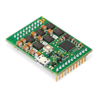
Figure 3-15 USB Socket J7
Note
Column “Head B” (
Table 3-9) refers to USB terminals of your PC.
Table 3-9 USB Socket J7 – Pin Assignment & Cabling
Table 3-10 USB Type A - micro B Cable
J7 &
Head A
Head B
Signal Description
Pin Pin
1 1
V
BUS
USB BUS supply voltage input +5 VDC
2 2 D− USB Data− (twisted pair with Data+)
3 3 D+ USB Data+ (twisted pair with Data−)
4 – ID not connected
5 4 GND USB ground
USB Type A - micro B Cable (403968)
Cable cross-section According to USB 2.0 / USB 3.0 specification
Length 1.5 m
Head A USB type “micro B”, male
Head B USB type “A”, male