Motherboard Design Guide
Design Guidelines
ESCON Module 50/5 Hardware Reference
5-36 CCMC | 2021-08 | rel9051
5.2 Design Guidelines
The following instructions are intended to serve as an aid for designing an application-specific motherboard
and ensuring the correct and reliable integration of the ESCON Module 50/5.
5.2.1 Ground
All ground connections (GND) should be internally connected to the ESCON Module 50/5 (equal potential).
It is customary to equip the motherboard with a ground plane. All ground connections should be connected
to the voltage supply ground via wide conductive tracks.
Table 5-13 Motherboard Design Guide – Grounding
If an earth potential is in place or required, the ground plane should be connected to the earth potential via
one or more capacitors. The use of ceramic capacitors with 100 nF and 100 V is recommended.
5.2.2 Layout
Guidelines for the layout of the motherboard:
• Connector pins [7] and [8] +V
CC
operating voltage:
The pins should be connected to the fuse via wide conductive tracks.
• Connector pins [9], [10] and [23] ground:
All pins should be connected with the ground of the operating voltage via wide conductive tracks.
• The width of the conductive track and the copper coating thickness of the conductors for supply
voltage and motor depend on the current required for the application. A minimum width of 75 mil is
recommended for the track and a minimum thickness of 35 μm for the copper coating.
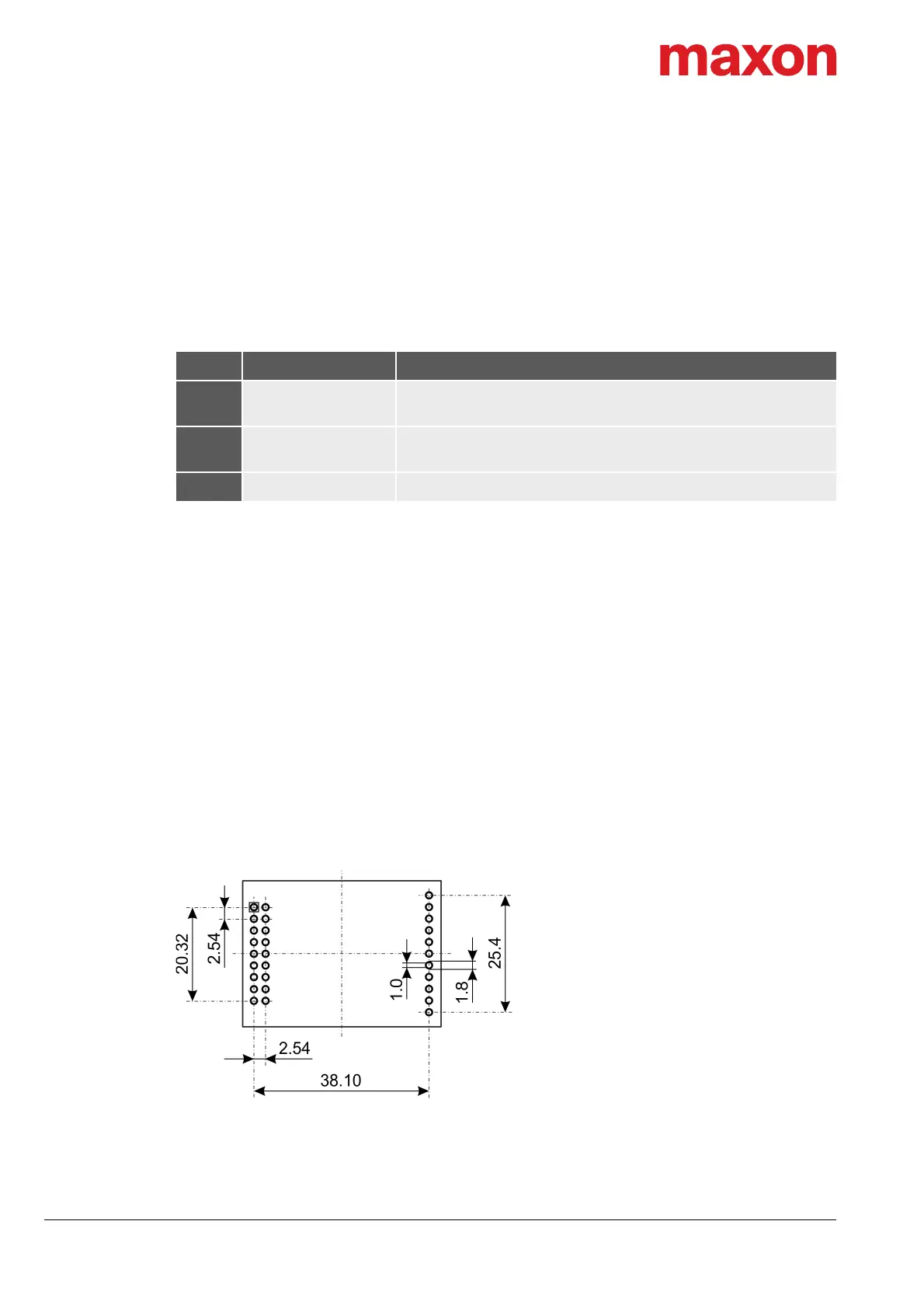
5.3 THT Footprint
Figure 5-26 THT Footprint [mm] – View from above
5.4 Pin Assignment
For detailed specifications chapter “3.3 Connections” on page 3-15.
Pin Signal Description
9
Power_GND
GND
Ground of operating voltage
Ground
10
Power_GND
GND
Ground of operating voltage
Ground
23 GND Ground