SENSOR PROBE INSTALLATION
Copyright © 2017 McCrometer, Inc. All printed material should not be changed or altered without permission of
McCrometer. Any published technical data and instructions are subject to change without notice. Contact your McCrometer
representative for current technical data and instructions.
www.mccrometer.com
3255 WEST STETSON AVENUE • HEMET, CALIFORNIA 92545 USA Printed In the U.S.A.
TEL: 951-652-6811 • 800-220-2279 • FAX: 951-652-3078 Lit. # 30120-48 Rev. 2.4 / 11-5-18
9
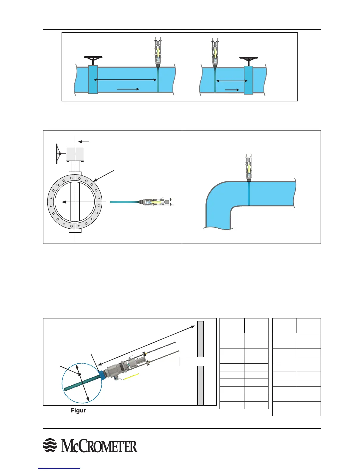
Figure 9. FPI Installed in Plane with Elbow
Figure 10. Sensor Clearance Distance
Figure 7. FPI Mag Installation Orientation With A Gate Valve Or Elbow
Rotational axis of a buttery valve
Buttery Valve
FLOW
VALVE
20D UPSTREAM
FPI
FLOW
VALVEFPI
1D DOWN-
STREAM
FLOW
VALVE
20D UPSTREAM
FPI
FLOW
VALVEFPI
1D DOWN-
STREAM
FLOW
VALVEFPI
1D DOWN-
STREAM
Install the FPI Mag
perpendicular to the
rotational axis of a
buttery valve
Figure 8. FPI Mag Installation Orientation With
A Buttery Valve
STEP 4: Verify Sucient Installation Clearance From Obstructions
The sensor installation hardware will protrude from the pipe during installation and when installed requiring
sucient clearance (distance H, the required installation clearance, in Figure 10 below) from any obstruction. This
distance accounts for the length of the sensor, the distance from the outer pipe wall to the top of the valve plus:
18" is recommended; 12" is the minimum.
Line Size
(Inches)
Distance
H
4" 51"
6" 51"
8" 55"
10" 55"
12" 59"
14" 59"
16" 59"
18" 63"
20" 63"
22" 67"
Line Size
(Inches)
Distance
H
24" 67"
30" 71.25"
36" 77.25"
42" 83.25"
48" 89.25"
54" 95.25"
60" 101.25"
66" 107.25"
72" 113.25"
78"-138"
Call
Factory
H
Line size
Not to scale
Obstruction

 Loading...
