SENSOR PROBE INSTALLATION
Copyright © 2017 McCrometer, Inc. All printed material should not be changed or altered without permission of
McCrometer. Any published technical data and instructions are subject to change without notice. Contact your McCrometer
representative for current technical data and instructions.
www.mccrometer.com
3255 WEST STETSON AVENUE • HEMET, CALIFORNIA 92545 USA Printed In the U.S.A.
TEL: 951-652-6811 • 800-220-2279 • FAX: 951-652-3078 Lit. # 30120-48 Rev. 2.4 / 11-5-18
5
Diagram
Number
Description
Part
Number
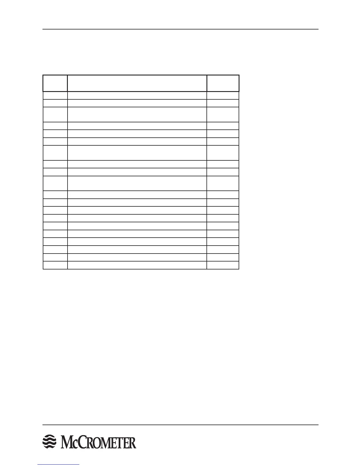
1 Top Plate for use with 3/8" retaining rods MIM043
1 Top Plate for use with 1/2" retaining rods MIM053
2 Sensor Assembly
Contact
Factory
3 Set screw (2 ea.) 920001001
4 Spring 920000901
4 Heavy Spring 920000903
5
2" Stainless Steel Full Port Ball Valve with SS Nipple
(Min. 1 7/8" dia. port)
43059-1
6 Compression Seal (3/4" sensor) MIM017-1
6 Compression Seal (1 -1/4" sensor) MIM012-1
7 Compression Seal Assembly
Contact
Factory
8 3/8" SS Long Threaded Rods (2 ea.) 64006
9 1/2" High Strength SS Short Threaded Rods (2 ea.) X6743
10 3/8" SS Nut (8 ea.) 93007
10 1/2" SS Nut (8 ea.) 10755
11 3/8" Locking Cotter Pin 921000701
11 1/2" Locking Cotter Pin 921000702
12 Captive Nut 42226
12 Captive Nut Bearing Retainer 42225
12 Captive Nut Bearing 92121
13 Protective Cap FPI-002RP
STEP 1: Sensor Parts List with Part Numbers
This manual refers to the part names of the sensor. It is important to be familiar with the parts and their names
when following the installation instructions.
The table below corresponds to the graphic in Figure 5.

 Loading...
