SENSOR PROBE INSTALLATION
Copyright © 2017 McCrometer, Inc. All printed material should not be changed or altered without permission of
McCrometer. Any published technical data and instructions are subject to change without notice. Contact your McCrometer
representative for current technical data and instructions.
www.mccrometer.com
3255 WEST STETSON AVENUE • HEMET, CALIFORNIA 92545 USA Printed In the U.S.A.
TEL: 951-652-6811 • 800-220-2279 • FAX: 951-652-3078 Lit. # 30120-48 Rev. 2.4 / 11-5-18
14
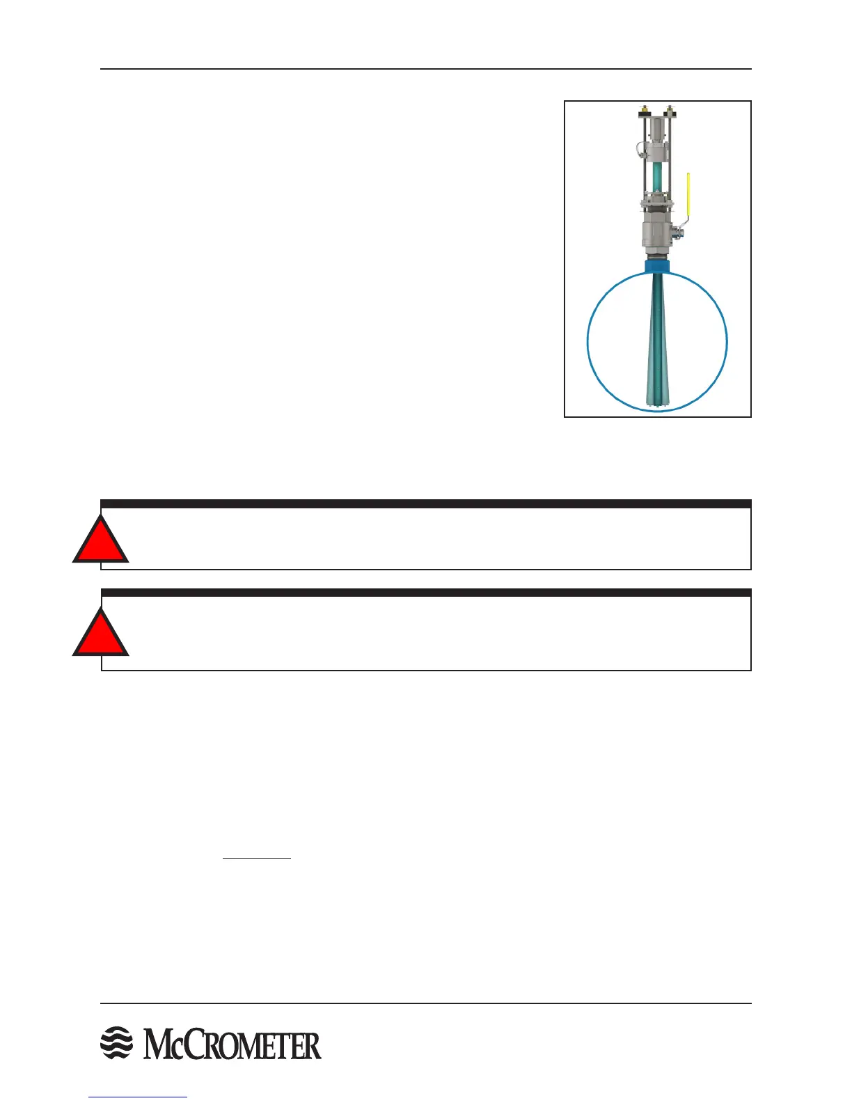
Figure 17. Sensor Vibration
STEP 10: Insert The Sensor
The sensor can be installed while the line is under owing conditions. The
line water velocity should be as low as possible to prevent sensor vibration
during the insertion process. The velocity must be under 5 ft/s.
Follow the steps below to insert the sensor into the pipe.
1. Hand tighten the compression seal bolts and nuts. DO NOT FULLY TIGHTEN THE COMPRESSION SEAL BOLTS
AND NUTS.
2. If the sensor is being installed under owing conditions follow this step. If not, proceed to the next step.
Barely crack open the valve to allow a little water into the compression seal assembly. Some water will leak
from the compressions seal. Lightly tighten compression seal bolts and nuts as required to minimize the
amount of water exiting the compression seal. A towel draped around the compression seal can reduce spray
if necessary.
3. Open the valve completely. Failure to open the valve completely will cause the valve to scrape the sensor
during insertions and may result in permanent damage to the sensor.
WARNING!
The compression seal/sensor assembly may be under pressure. Serious injury may result if proper
procedures are not followed. Do not attempt to install the sensor without the retaining rods fully assembled.
!
WARNING!
If the meter was disassembled to assist in the installation of the compression seal assembly onto the valve
(STEP 7 and STEP 9) it is important to ensure that the meter is properly reassembled with both retaining
rods completely installed with the 3/8" or 1/2" nuts properly tightened.
!

 Loading...
