SENSOR PROBE INSTALLATION
Copyright © 2017 McCrometer, Inc. All printed material should not be changed or altered without permission of
McCrometer. Any published technical data and instructions are subject to change without notice. Contact your McCrometer
representative for current technical data and instructions.
www.mccrometer.com
3255 WEST STETSON AVENUE • HEMET, CALIFORNIA 92545 USA Printed In the U.S.A.
TEL: 951-652-6811 • 800-220-2279 • FAX: 951-652-3078 Lit. # 30120-48 Rev. 2.4 / 11-5-18
12
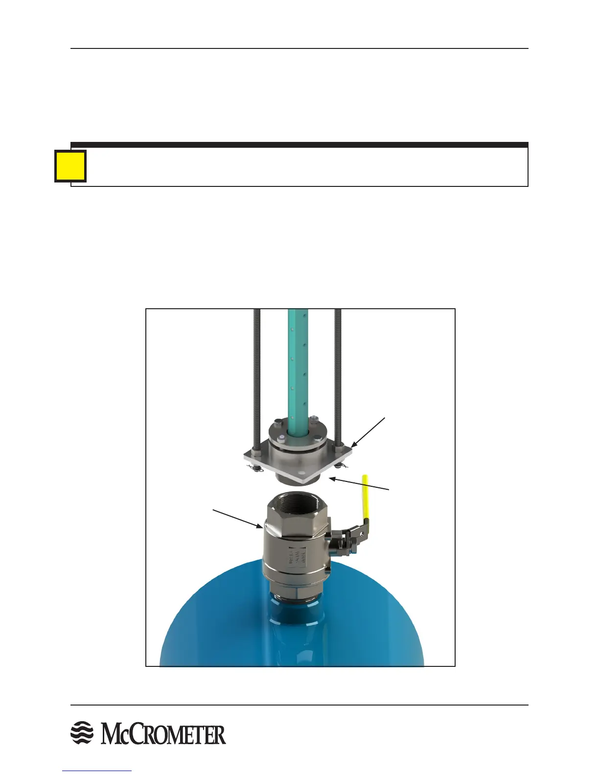
Figure 15. Sensor Installation
STEP 8: Sensor Installation Onto Pipe Valve
The sensor assembly uses a compression seal, which keeps the sensor watertight when the pipe is under pressure.
Care must be taken when installing the sensor to avoid leaks. Follow the steps below to install the sensor onto
the pipe valve:
1. Put a generous amount of the supplied pipe sealant on the compression seal threads. Teon tape may also
be used.
i
Compression
Seal Threads
Bottom Plate
Compression
Seal Assembly
Pipe Valve
IMPORTANT
If pipe sealant gets on the sensor electrodes the velocity signal may be lost. Use care when applying
the sealant to the compression seal threads.
2. Place the compression seal threads over the pipe valve. Turn the entire sensor assembly clockwise to secure
the assembly to the valve. A large pipe wrench can be used to grip the bottom plate of the compression seal
to tighten the assembly into the pipe valve.
3. The seal is secure when a large amount of force is required to turn the assembly.
4. The sides of the bottom plate should be parallel with the pipe.
5. Locate the ow direction arrow on the top plate and align it with the direction of the ow in the pipe.

 Loading...
