SENSOR PROBE INSTALLATION
Copyright © 2017 McCrometer, Inc. All printed material should not be changed or altered without permission of
McCrometer. Any published technical data and instructions are subject to change without notice. Contact your McCrometer
representative for current technical data and instructions.
www.mccrometer.com
3255 WEST STETSON AVENUE • HEMET, CALIFORNIA 92545 USA Printed In the U.S.A.
TEL: 951-652-6811 • 800-220-2279 • FAX: 951-652-3078 Lit. # 30120-48 Rev. 2.4 / 11-5-18
17
STEP 13: Installing The Short Retaining Rods
After the sensor has been inserted and the load adjusted, shorter retaining rods can be installed and the longer
ones removed. This will make the sensor assembly more compact.
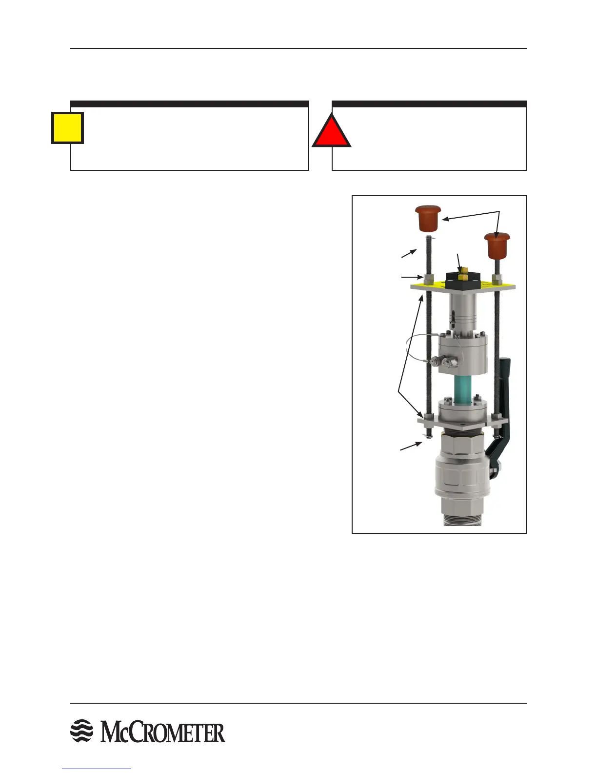
Figure 22. Installed Short Retaining Rods
Follow the steps below to install the short retaining rods:
1. Insert the two short retaining rods through the two holes in
the top plate opposite the two captive nuts with the long
retaining rods. Once the short retaining rods are passed
through the top plate, thread one nut per rod onto the
bottom of the rod about one inch from the bottom.
2. Insert the two short rods end through the corresponding
holes on the compression seal bottom plate. Thread a nut
onto the bottom of each short retaining rod.
3. Tighten the nuts above and below the compression seal
bottom plate to secure the short retaining rods to the bottom
plate and to prevent the short retaining rods from spinning.
4. Attach a locking cotter pins to bottom ends of the short
retaining rods.
5. Secure the short retaining rods to the top plate with one 3/8"
or 1/2" nuts per rod.
6. Remove the long retaining rods and store in a safe, dry
location tagged with the meter serial number.
7. Check and adjust the "Sensor Load" as necessary. See STEP
12.
8. Secure the 3/8” or 1/2" nuts on the top plate by running a
second jam nut down and tightening it against the rst nut.
9. Attach a locking cotter pin to the top ends of the short
retaining rods.
10. Place the protective caps on the ends of the two retaining
rods over the cotter pins.
IMPORTANT
The long retaining rods are matched to each sensor
and are required for removal of the sensor. It is
important to safely store the long retaining rods and
label them with the meter serial number.
i
!
WARNING!
Do not remove the long installation rods
until the short retaining rods are secured
with cotter pins.
Locking
Cotter Pin
Locking
Cotter Pin
Nuts
Short
Retaining
Rods
Captive
Nut
Protective
Caps

 Loading...
