SENSOR PROBE INSTALLATION
Copyright © 2017 McCrometer, Inc. All printed material should not be changed or altered without permission of
McCrometer. Any published technical data and instructions are subject to change without notice. Contact your McCrometer
representative for current technical data and instructions.
www.mccrometer.com
3255 WEST STETSON AVENUE • HEMET, CALIFORNIA 92545 USA Printed In the U.S.A.
TEL: 951-652-6811 • 800-220-2279 • FAX: 951-652-3078 Lit. # 30120-48 Rev. 2.4 / 11-5-18
11
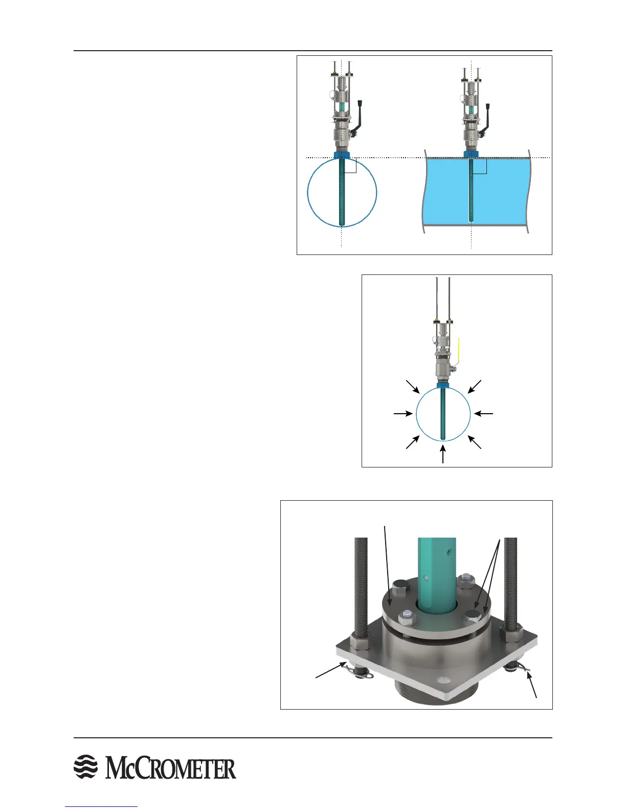
STEP 6: Ensure correct sensor orientation
The FPI should be installed perpendicular to the
pipe as shown in Figure 12 for a vertical installation.
The allowable tolerance for installation is ± 0.5°. A
perpendicular installation is determined by the
coupling that is mounted on the pipe. Prior to
installing the FPI a level ruler should be used to
check the coupling and ensure that it sits level.
The FPI will not be perpendicular to the pipe if the
coupling does not sit level. Do not install the sensor
if the coupling is not mounted perpendicular to
the pipe.
The FPI sensor can be installed at any point around
the pipe diameter, providing the sensor maintains
proper orientation as shown in Figure 13.
90°
90°
Figure 13. Sensor installation points
around pipe diameter
Figure 12. Sensor at 90° relative to pipe
Compression Seal
Lower Retaining
Rod Nut
Locking
Cotter Pin
Compression Seal
Bolt And Nut
Figure 14. Compression seal removal
STEP 7: Optional Compression Seal Disassembly For
Installation Of Large Sensors
The sensor assembly can be installed onto the pipe valve
as a whole unit. On larger pipe size installations this can be
cumbersome or impractical. In such cases the compression seal
assembly can be removed from the sensor for easier installation
onto the pipe valve. Once the compression seal assembly is
installed onto the pipe valve, then the sensor can be re-installed
into the compression seal assembly.
NOTE: if this step is skipped, proceed to STEP 8.
The following steps describe the separation of the sensor, top-
plate and retaining rods from the compression seal assembly.
1. The compression seal has two bolts and two studs with
nuts. Loosen the bolts and nuts on the compression seal
relieving the pressure on the compression seal. DO NOT
REMOVE THE BOLTS OR NUTS.
2. On the compression seal assembly,
remove the locking cotter pins from the
bottom of the two retaining rods under
the 3/8" or 1/2" nuts.
3. Remove the lower 3/8" or 1/2" nuts from
the retaining rods.
4. Slide the sensor out of the compression
seal. The retaining rods will also slide
out of the compression seal assembly.
Carefully set the sensor and attached
hardware to the side.
5. At this point the compression seal
assembly can be installed onto the valve.
FPI sensor may
be inserted at any
point around the
pipe diameter.

 Loading...
