SENSOR PROBE INSTALLATION
Copyright © 2017 McCrometer, Inc. All printed material should not be changed or altered without permission of
McCrometer. Any published technical data and instructions are subject to change without notice. Contact your McCrometer
representative for current technical data and instructions.
www.mccrometer.com
3255 WEST STETSON AVENUE • HEMET, CALIFORNIA 92545 USA Printed In the U.S.A.
TEL: 951-652-6811 • 800-220-2279 • FAX: 951-652-3078 Lit. # 30120-48 Rev. 2.4 / 11-5-18
13
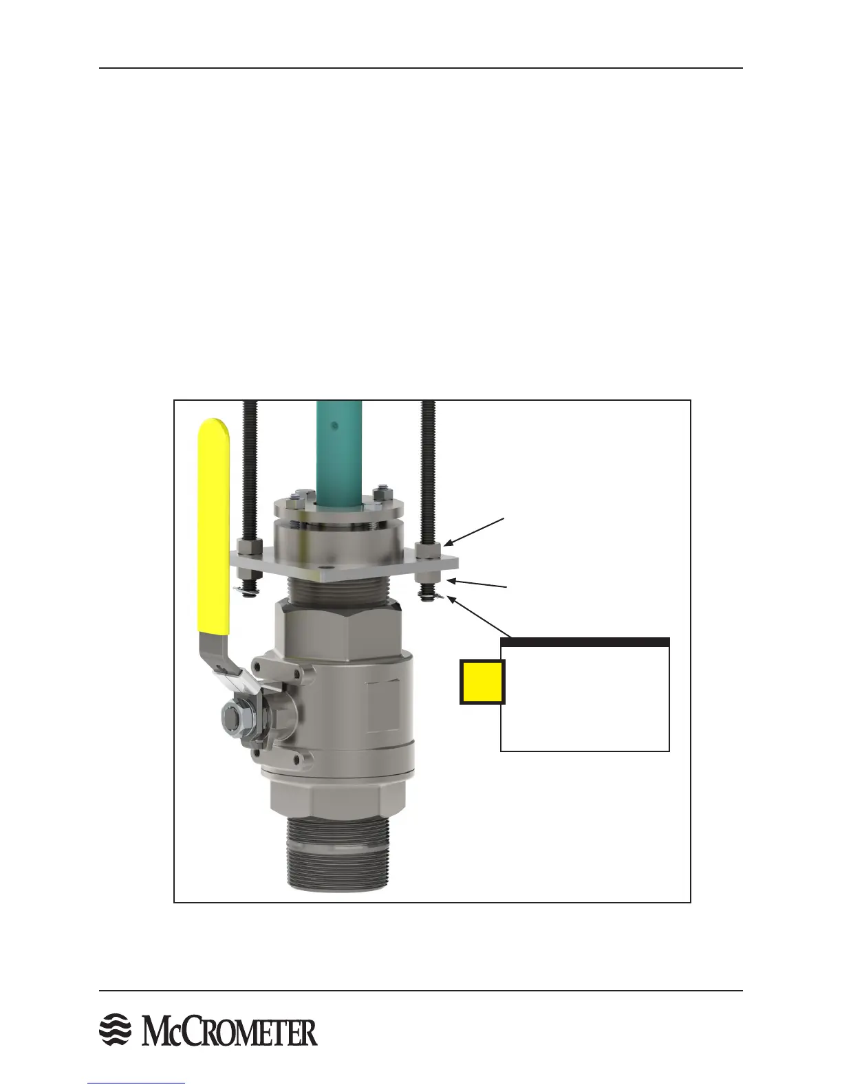
Figure 16. Compression Seal Reassembly
STEP 9: Sensor Re-assembly After Optional Compression Seal Assembly Installation
NOTE: use this step if you removed the compression seal assembly (STEP 7) and installed it onto the pipe valve
separate from the sensor. If you installed the sensor without disassembling it, proceed to the next step.
After the compression seal has been installed onto the pipe valve, follow the steps below to reassemble the sensor
into the compression seal assembly:
1. Apply water or Simple Green to the interior surface of the rubber seal gland. This will act as a lubricant
to facilitate the insertion of the sensor and ensure its proper axial loading.
2. Insert the sensor into the compression seal in the bottom plate while inserting the two retaining rods
into their respective holes in the bottom plate and secure with one 3/8" or 1/2" nut above and one
below the bottom plate.
3. Ensure the two nuts above and below the compression seal assembly are suciently tightened to
prevent the threaded rod from rotating.
4. Insert the locking cotter pins through the small holes in the bottom of the retaining rods, just below
the bottom 3/8" or 1/2" nuts.
IMPORTANT!
When inserting the
retaining rods, ensure
the end has a hole for
the locking cotter pin.
i
Nut Above The
Bottom Plate
Nut Below The
Bottom Plate

 Loading...
