SENSOR PROBE INSTALLATION
Copyright © 2017 McCrometer, Inc. All printed material should not be changed or altered without permission of
McCrometer. Any published technical data and instructions are subject to change without notice. Contact your McCrometer
representative for current technical data and instructions.
www.mccrometer.com
3255 WEST STETSON AVENUE • HEMET, CALIFORNIA 92545 USA Printed In the U.S.A.
TEL: 951-652-6811 • 800-220-2279 • FAX: 951-652-3078 Lit. # 30120-48 Rev. 2.4 / 11-5-18
15
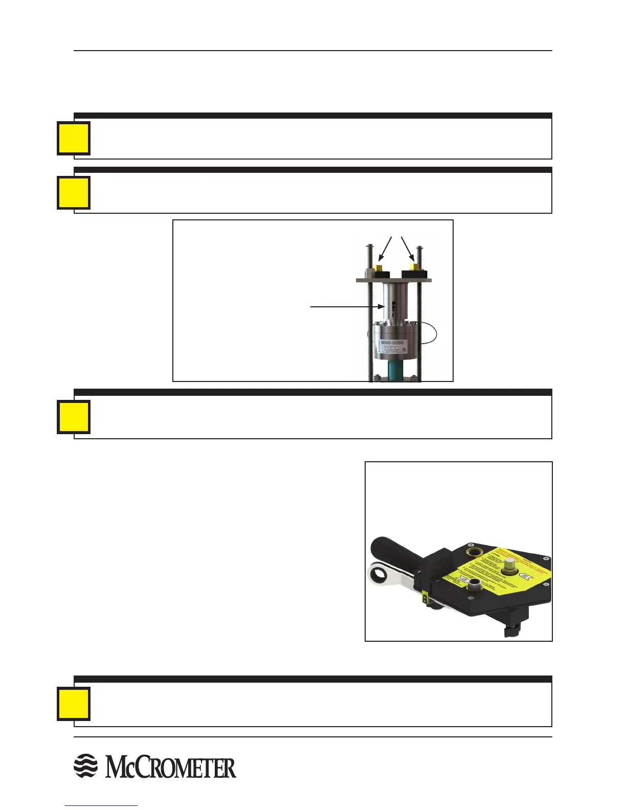
Figure 18. Captive Nuts
IMPORTANT
If the captive nuts are not tightened simultaneously, the top plate will become crooked and cause the
sensor to be inserted at an angle and may cause permanent damage to the sensor.
i
NOTE
If the short retaining rods are not used (see STEP 13), run a 3/8" or 1/2" nut down against each captive nut
to prevent the captive nut from rotating.
i
Rotate captive nuts clockwise
simultaneously to insert sensor
Set Screw For Load Spring
Captive Nuts
IMPORTANT
It is recommended that the Sensor Insertion Tool be used to rotate the captive nuts to ensure the top plate
compresses evenly. See STEP 11.
i
4. Insert the sensor into the pipe by simultaneously rotating the two captive nuts on the top plate clockwise (See
Figure 18) with the provided 9/16" ratchet wrenches or the Sensor Insertion Tool (See STEP 11) until the foot
of the sensor reaches the far wall of the pipe and the load spring starts to compress. Compression of the load
spring is indicated by the movement of the set screw on the top plate. See STEP 12.
Figure 19. Insertion Tool
STEP 11: Using The Sensor Insertion Tool - Optional
McCrometer recommends using a Sensor Insertion Tool (see Figure
19) to help with inserting the sensor and to avoid any damage to
the sensor.
Follow the steps below to use the Sensor Insertion Tool:
1. Place the Sensor Insertion Tool over the retaining rods and
slide the retaining rods through the holes in the tool until it
sits over the captive nuts.
2. Lock it into place with spring locks located on the bottom of
the tool.
3. Using the provided wrench rotate the high gear shaft clockwise
until the bottom of the sensor reaches the far wall of the pipe
as indicated in STEP 10. The low gear shaft is used to apply
pressure to the sensor once the sensor has reached the far wall
of the pipe. See STEP 12.
3/8" Insertion Tool (Part Number 75031)
for TSL < 72" and pressure < 200 psi
1/2" Insertion Tool (Part Number 75032)
for TSL > 72" or pressure > 200 psi
IMPORTANT
Large line size meters or applications with high pressure may use 1/2" retaining rods. When ordering the
Sensor Insertion Tool specify the size required. (P/N 75031 for 3/8" or P/N 75032 for 1/2")
i

 Loading...
