SENSOR PROBE INSTALLATION
Copyright © 2017 McCrometer, Inc. All printed material should not be changed or altered without permission of
McCrometer. Any published technical data and instructions are subject to change without notice. Contact your McCrometer
representative for current technical data and instructions.
www.mccrometer.com
3255 WEST STETSON AVENUE • HEMET, CALIFORNIA 92545 USA Printed In the U.S.A.
TEL: 951-652-6811 • 800-220-2279 • FAX: 951-652-3078 Lit. # 30120-48 Rev. 2.4 / 11-5-18
7
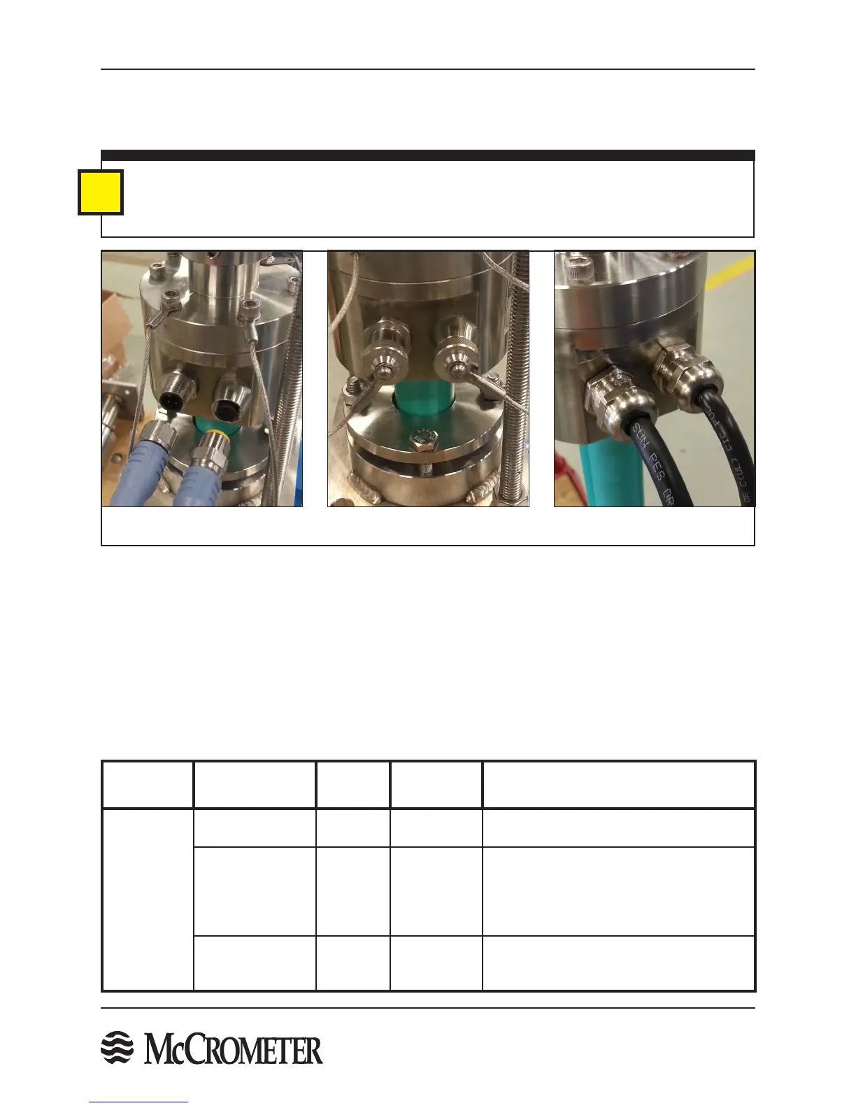
STEP 2: Detach The Cable Quick Connects
The sensor cable is tted with an IP68 rated Quick Connect tting at the sensor connection. For ease of installation,
remove the cable from the sensor and set aside. Compression gland seals are available as an option instead of the
Quick Connect cable ttings.
IMPORTANT: When the Quick-Connect cable connection is not attached to the sensor, ensure that
the threaded caps are attached to the sensor connection and the cable connection to keep the wire
connectors free of dirt and corrosion. When the cable is connected to the sensor, connect the end caps
together to keep their interior free from dirt and corrosion.
i
Quick Connect Cables Fittings With End Caps
Optional Compression Gland
Cable Fittings
STEP 3: Verify Sensor Installation Location - Upstream And Downstream Straight-Pipe Run Recommendations
Figure 6. Sensor Cable Fittings
Flow disturbers such as partially open valves cause ow disturbances that can adversely aect ow meter accuracy.
The table below provides suggestions for the placement of the FPI Mag sensor upstream and downstream
of common ow disturbers to meet specication accuracy. The upstream and downstream straight-pipe
recommendations are conservative, based on research completed in the McCrometer NIST traceable calibration
facility. In many cases, the installation distances suggested below can be shortened depending on ow conditions
and piping layout.
Upstream and Downstream Straight Pipe Run Recommendations
Flow
Disturbance
Condition Upstream Downstream Notes
Buttery
Valve
100% Open 2D 1D
Meter should be installed perpendicular to
the axis of rotation of the valve - See Figure 8
Non-Actuated
Control Valve
5D 1D
For Buttery Valves that remain in a constant
position between 50% to 100% open
during operation. Meter should be installed
perpendicular to the axis of rotation of the
valve - See Figure 8
Actuating Control
Valve
20D; See
Note and
Figure 7
2D
Recommended to install the sensor 2D
upstream of the Automated Control Valves

 Loading...
