30119-50 Rev. 2.2 | 23JUL2020
Page 8
INSTALLATION
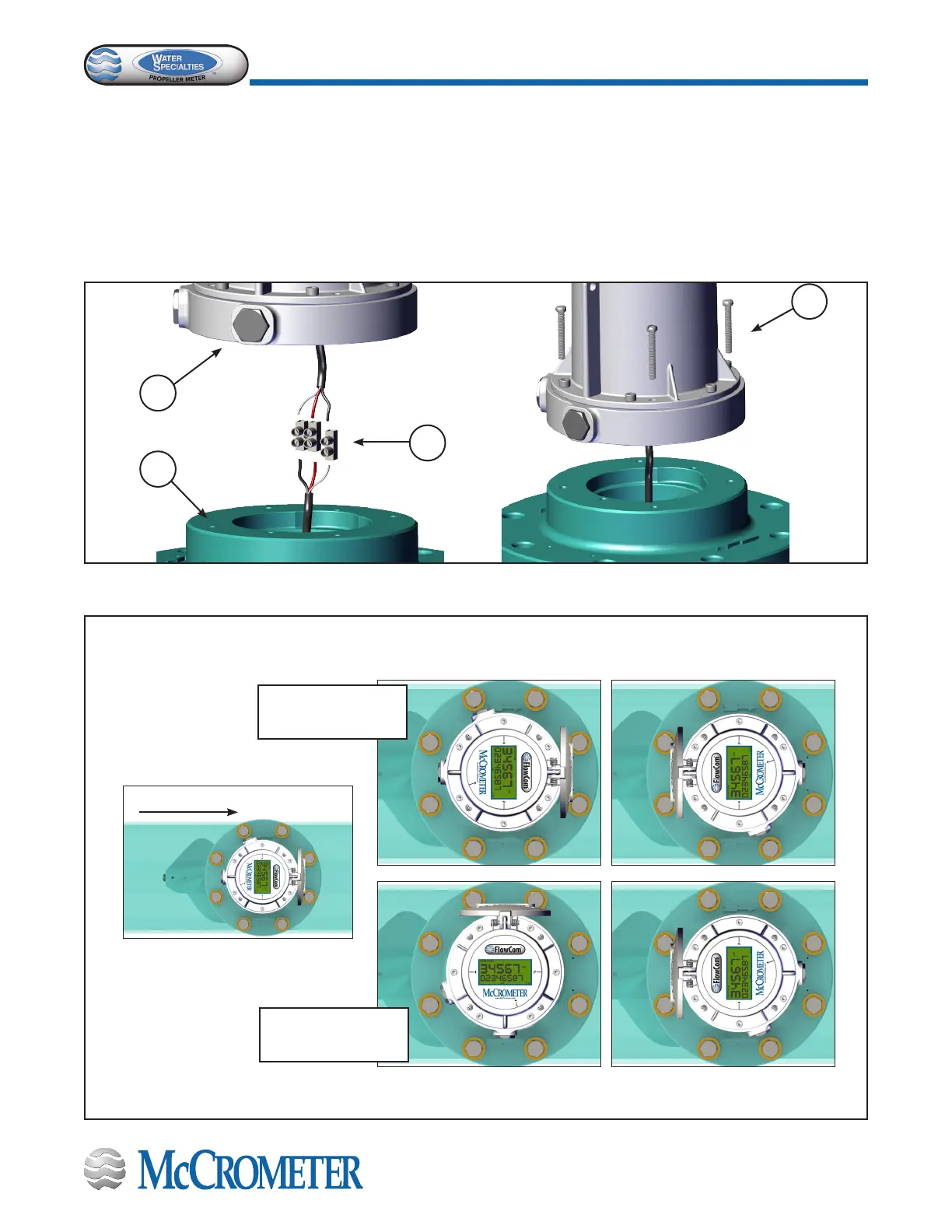
STEP 5: Connecting the sensor wires
The connection shown below is typical of all Water Specialties Electronic Propeller Flow Meters.
a. Clean the meter head surface of all dirt, glue, gaskets, etc.
b. Verify that an O-ring is installed at the bottom of the electronic register base plate.
c. Connect the sensor cable to the in-line terminal blocks.
d. Secure the electronic register to the meter head with the four 1-1/4” long screws provided (Figure18).
e. Spin the propeller and verify that the rate display responds.
a
b
c
d
NOTE: When the FlowCom is attached to the base plate, it can be oriented in four possible ways. This aects
how the register is read when the owmeter is installed in the pipe. Select the orientation you prefer as shown
below in Figure 4.
Figure 4. FlowCom Mounting Orientation
FlowCom oriented in
line with the pipe
FlowCom oriented at
90° with the pipe
Direction of water ow
x4
 Loading...
