30119-50 Rev. 2.2 | 23JUL2020
Page 7
INSTALLATION
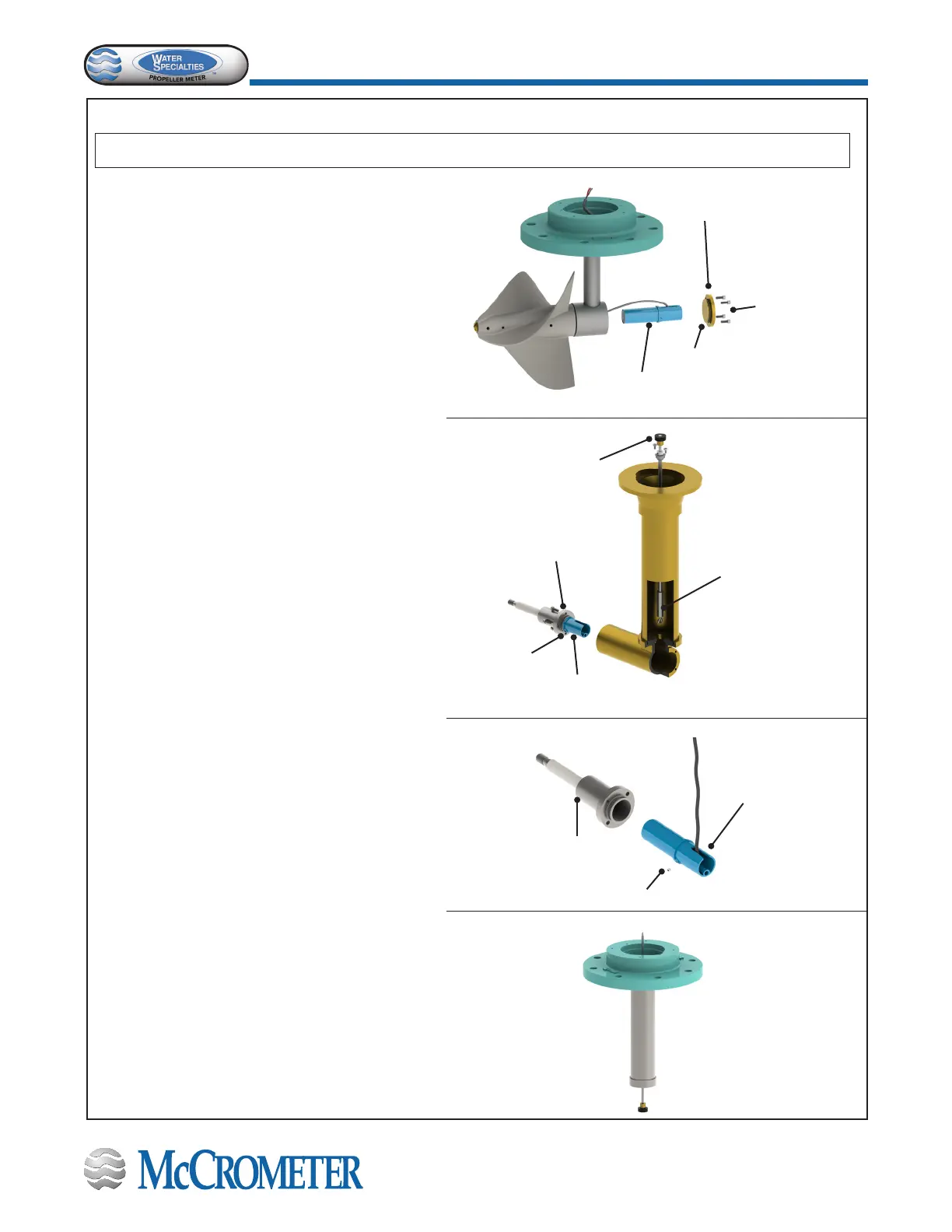
Back Plate
Mounting
Screws
Back Plate
O-ring
Sensor Assembly
Separator-spindle
Assembly
Vertical Shaft
Pulling Fixture
T-2730-2
Sensor Assembly
Separator-spindle
Assembly
Set Screw
Set Screw
Sensor
Assembly
For ML and LP meters: Push the sensor assembly
through the back of the gearbox all the way into
the separator/spindle assembly. Rotate the sensor
assembly so that the sensor cable can be fed
through gearbox up over the meter head. Put a thin
lm of silicon grease on the O-ring and secure the
back plate of the gearbox with four screws.
Note: Do not twist the back plate. This can cause the
O-ring to be pinched and the meter to leak.
For OF and 24” to 54” ML meters: Attach pulling
xture T-2730-2 to bottom tip of existing vertical
shaft assembly. Tighten both set screws on the
xture with a 0.062 Allen wrench for a secure
connection to the vertical shaft tip. Loop sensor
cable through hook on xture and secure with a
small piece of tape. Keep the sensor cable tight to
allow passage through drop pipe bushings.
For VF meters: Push the sensor assembly all the
way into separator/spindle assembly and then
tighten the set screw to secure the position of the
sensor assembly.
Note: The sensor cable must be positioned as
shown.
Then tie the sensor cable to the magnet end of the
vertical shaft to assist in pulling the cable through.
Leave approximately a 4” tale from the knot to the
end connector so that magnet and cables can pass
through the drop pipe end. At last, reinstall the
propeller and separator/spindle assembly.
STEP 4: Reassemble the gearbox assembly.
Before you begin, make sure the gearbox or drop pipe and separator/spindle assembly are dry and free of oil.
 Loading...
