30119-50 Rev. 2.2 | 23JUL2020
Page 10
INSTALLATION
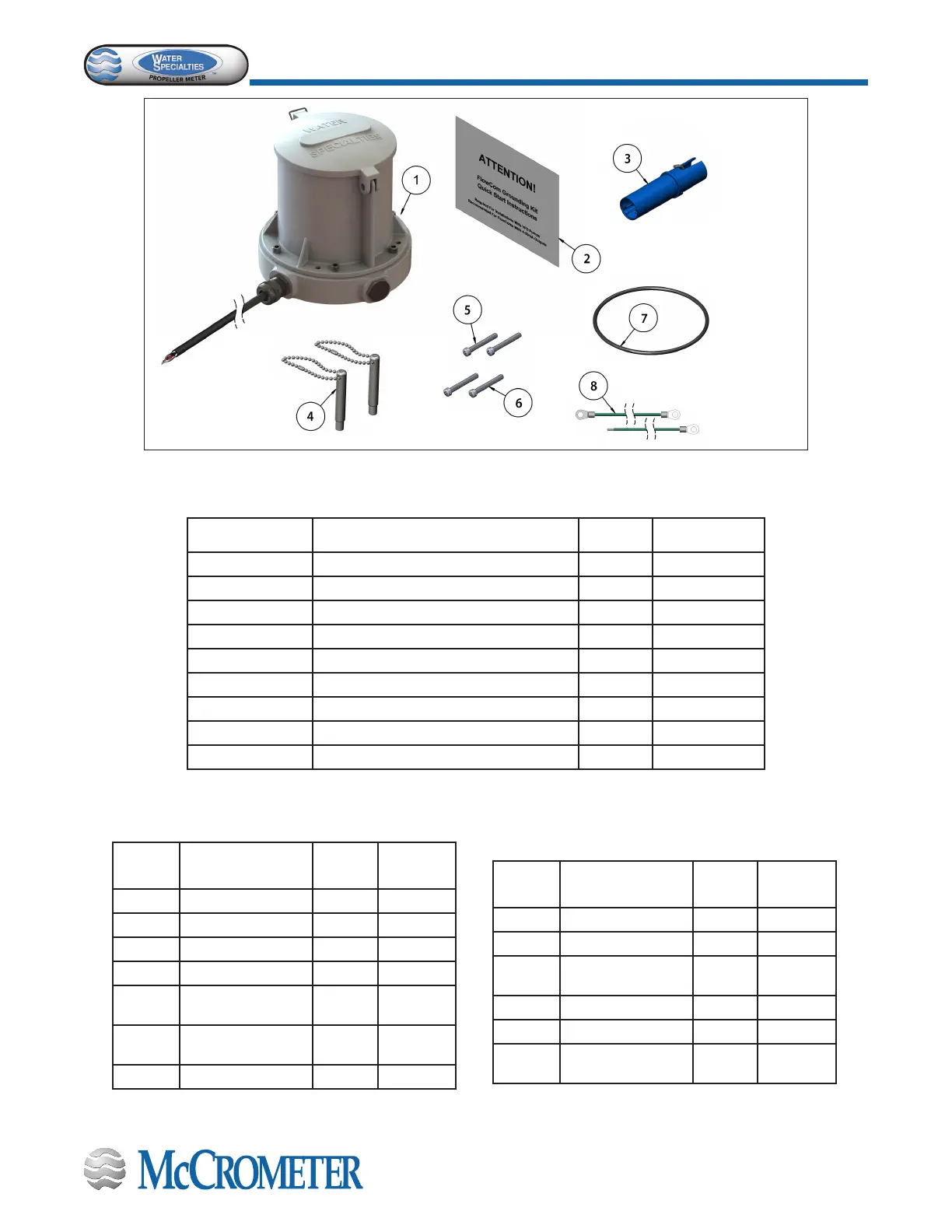
Figure 6. Conversion Kit for Tables Shown Below
For FlowCom models FC101-01-R, FC101-02-R, FC101-03-R. Refer to Figure 6 above.
Parts Diagram Description Quantity Part Number
1 FlowCom Unit 1 FC101-01
Bagged parts:
2 Grounding Kit Instructions 1 30110-18
3 Sensor 1 4-2745-2
4 Magnet Wand 2 FC100-M
5 Screw 10-32 x 1.25” Long 2 10730
6 Screw 10-32 x 1.25” Long w/hole 2 10830
7 O-Ring (243 Buna) 1 1-1551-38
8 Green Wire 1 1-1706-18-1
For FlowCom model FC101-00-R.
Refer to Figure 6 above.
Parts
Diagram
Description
Quantity
Part
Number
1 FlowCom Unit 1 FC101-01
Bagged parts:
3 Sensor 1 4-2745-2
4 Magnet Wand 2 FC100-M
5
Screw 10-32 x
1.25” Long
2 10730
6
Screw 10-32 x
1.25” Long w/hole
2 10830
7 O-Ring (243 Buna) 1 1-1551-38
For FlowCom models with remote: FC101-00-R,
FC101-01-R, FC101-02-R, FC101-03-R.
Refer to Figure 6 above.
Parts
Diagram
Description
Quantity
Part
Number
1 FlowCom Unit 1 FC101-01
Bagged parts:
2
Grounding Kit
Instructions
1 30110-18
3 Sensor 1 4-2745-2
4 Magnet Wand 2 FC100-M
8 Green Wire 1
1-1706-
18-1
 Loading...
