30119-50 Rev. 2.2 | 23JUL2020
Page 5
INSTALLATION
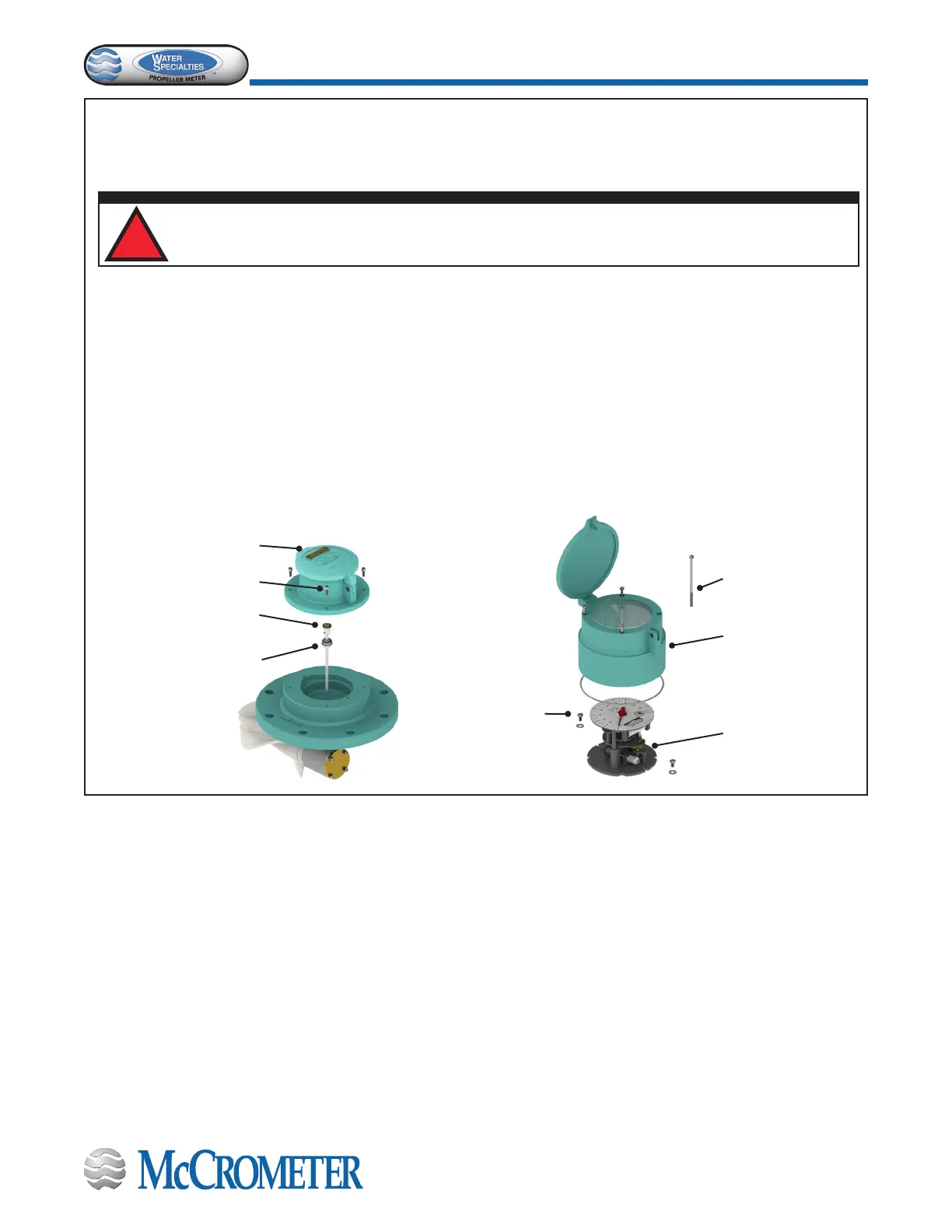
STEP 2: Remove the totalizer assembly.
Remove the entire totalizer or indicator-totalizer register assembly. Register models with totalizers have four bonnet
screws and models with both the indicators and totalizers have four bonnet screws and two register screws. Remove
the shaft.
Totalizer Assembly
Bonnet Screws
Vertical Shaft
Vertical Shaft
Mounting Screws
Bonnet Screws
Indicator-totalizer
Mounting Screws
Indicator-
totalizer
Assembly
Bonnet
For ML and LP meters: Remove the V-shaft by
loosening the two screws holding the V-shaft from
the inside of the meter head.
For ML and LP meters with extensions and for OF and VF
meters: Pull vertical shaft out only enough (approximately
1”) for removal of miter gear frame assembly so that the
vertical shaft can be used later for pulling the sensor input
cable out of the drop pipe.
STEP 1: Remove the owmeter.
Remove pressure from the pipeline.
Remove the entire owmeter from the pipeline.
CAUTION!
Never remove a meter or top plate assembly while the line is under pressure!
!
 Loading...
