6
4 - ASSEMBLY INSTRUCTIONS
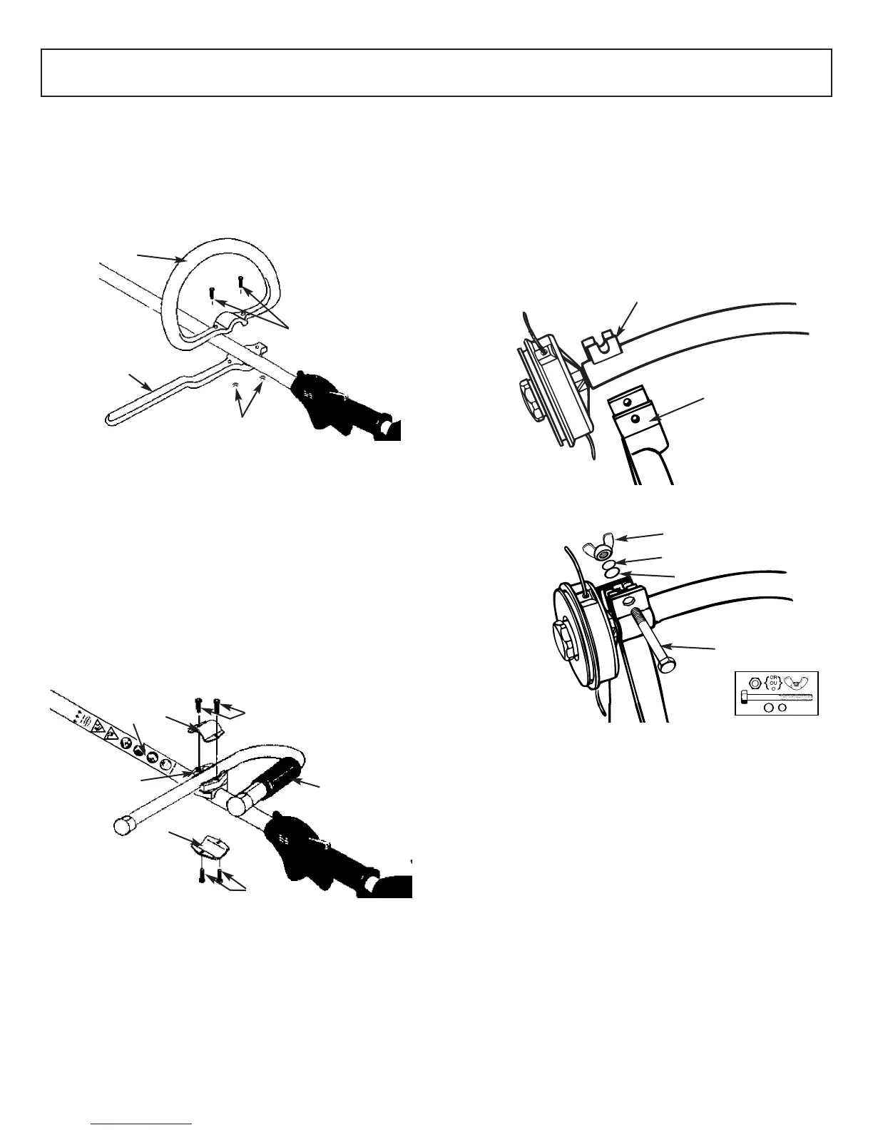
4-1. “P” HANDLE ASSEMBLY (MT3025)
1. To install handle onto unit, you will need the following
components from y
our user kit: “P” handle (A & B),
screws (C) and nuts (D). (Figure 4-1A).
2.
Install the handle (B) on the shaft 160-200mm from
throttle and tighten the 2 screws (C) and nuts (D).
4-2. “J” HANDLE ASSEMBLY (MT30725)
1. To install handle onto unit, you will need the following
components from your user kit: “J” handle (A), middle
clamp housing (B), upper and lower clamps (C) and
screws (D). (Fig. 4-2A)
2. Install the middle clamp housing (B) on the shaft near
the arrows on the sticker (warning label E ), put the low-
erclamp (C) under shaft and tighten with 2 screws (D).
3. Install the J handle (A) on the middle clamp housing,
then put the upper clamp (C) over J-handle and tighten
the other 2 screws (D).
4-3. DEBRIS SHIELD
WARNING
The debris shield must be installed (Figure 4-3A) to prop-
erly dispense cutter line and protect operator.
Shield fits snug on shaft. Some force may be required.
1. Seat shield (A) onto shaft bracket (B). (Fig. 4-3A)
2. Insert bolt (C), washer (D), lock washer (E) and wing
nut (F), tighten securely. (Fig. 4-3B)
4-1A
5
3 - SAFETY PRECAUTIONS
A
B
C
D
4-2A
B
C
A
C
D
D
E
Use of these personal safety items is highly recommended to
reduce the r
isk of accidental injury.
Minimum operating distance
3-3. INTERNATIONAL SYMBOLS
Do not use blade on this unit.
Read the User Manual.
Pump the primer bulb 10 times.
4-3A
B
4-3B
F
A
E
D
C