Rigid
0.7
1.0
1.3
1.7
2.0
Torque Nm / (ft -lb)
18 (13.3)
42 (31.0)
55 (40.6)
65 (48.0)
78 (57.6)
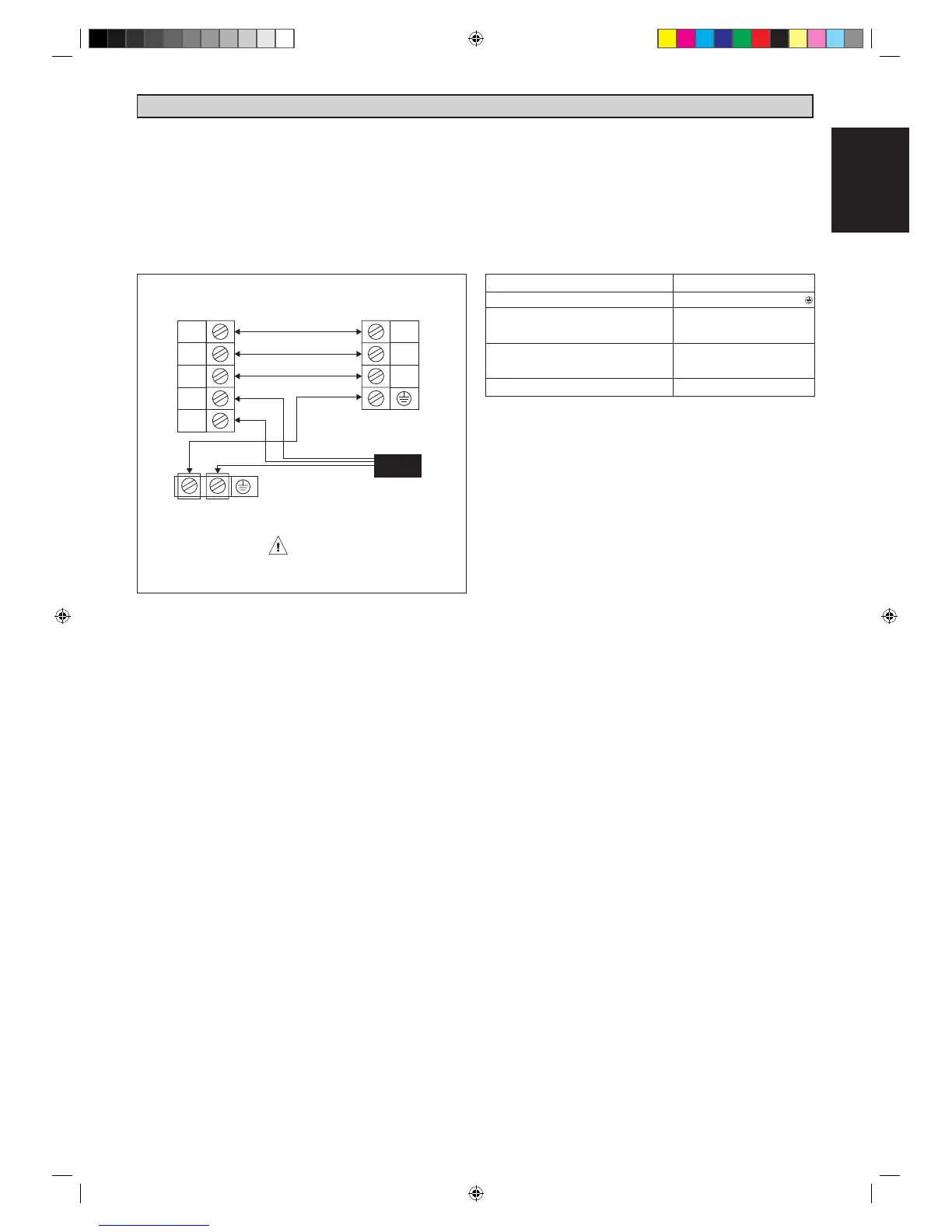
ELECTRICAL WIRING CONNECTION
IMPORTANT :* The figures shown in the table are for information purpose only. They should be checked and
selected to comply with the local/national codes of regulations. This is also subject to the type of
installation and conductors used.
** The appropriate voltage range should be checked with label data on the unit.
• All wires must be firmly connected.
• All wires must not touch the refrigerant piping
compressor or any moving parts of the fan motor.
• The connecting wires between the indoor unit and the
outdoor unit must be clamped on the wire clamps.
• The power supply cord must be equivalent to H07RN-
F(245IEC57) which is the minimum requirement.
Model 10/15
Voltage range
Power supply cable size* mm²
Number of core
Interconnection cable size mm²
Number of core
Recommended time delay fuse A
220V - 240V / 1Ph / 50Hz+
1.5
3
1.5
4
15
* If the length of the cable is more than 2m, use cable
with bigger size.
1
2
SIG
N
L
2
1
SIG
Indoor Unit
Terminal Block
Outdoor Unit
Terminal Block
Power Supply
Cable
There must be a double pole switch with
a minimum 3mm contact gap and fuse/
circuit breaker as recommended in the fixed
installation circuit.
Acson IM-WMJ-0109(0).indd 9 2009-4-8 9:10:13
 Loading...